Have you ever received casting or injection molded parts with visible scratches, gouges, or fine lines running across the surface? Do these seemingly minor “drag marks” keep showing up in quality inspections or, worse, get your shipments rejected?
Don’t underestimate them. Drag marks not only affect surface appearance, but can also compromise dimensional accuracy, interfere with assembly, and even shorten product lifespan. Often, they point to deeper issues—poor mold design, insufficient draft angles, improper ejection, or cooling imbalances—that could lead to costly rework, scrap, and damaged customer relationships.
In this article, I’ll break down the root causes of drag marks across casting, die casting, and injection molding processes—sharing practical solutions we’ve tested and refined on our own production lines.
What Are Drag Marks?
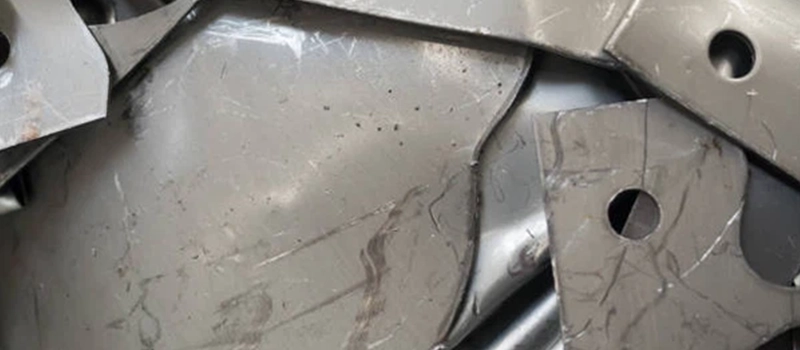
Have you ever noticed fine lines, scratches, or gouges running along the surface of a freshly manufactured casting or molded part? Those are what we call drag marks.
In the metal manufacturing world, drag marks refer to linear surface imperfections that typically appear on components made through casting or injection molding processes. These defects are often unintentional, and while they might look cosmetic at first, they can hint at deeper issues in your tooling, mold design, or process control.
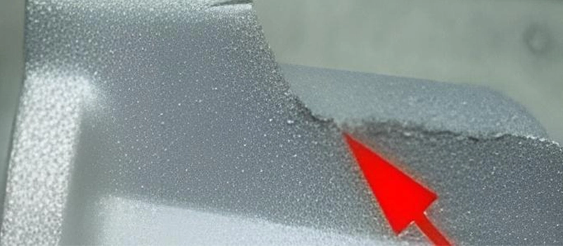
These marks usually follow the direction in which a part was pulled or ejected from a mold cavity. They may appear:
- As light scuff lines on plastic parts (in injection molding)
- As deep scratches or gouges on metal castings
- Along draft angles, ribs, or edges where friction was high during release
Their appearance can be subtle or severe depending on material type, surface finish, mold condition, and ejection force.
More Than Just a Cosmetic Issu
Some manufacturers and buyers dismiss drag marks as “surface-only problems”, but that’s a risky assumption.
In some cases, drag marks:
- Interfere with sealing surfaces
- Compromise precision fits
- Lead to part rejection
- Indicate inconsistent tooling pressure or damage
- Result in rework or scrapping costs
What They’re Not
To avoid confusion, drag marks are not the same as:
- Sink marks (caused by uneven cooling or material shrinkage)
- Flash (excess material at parting lines)
- Weld lines (joining of two flow fronts)
Instead, drag marks are purely mechanical friction-related defects that happen during mold-part separation, whether in metal casting, die casting, or plastic injection molding.
Why Are Drag Marks a Problem in Manufacturing?
Drag marks are often underestimated, especially by those new to metal casting or injection molding. At a glance, they may seem like superficial flaws—harmless scuffs or aesthetic imperfections. But in industrial manufacturing, especially in precision applications, drag marks are far more serious. Their presence can trigger functional issues, reputational damage, and financial loss.
Functional Consequences on End Products
First, let’s talk about the functionality of parts. In industries like automotive, aerospace, medical, or industrial equipment, dimensional accuracy and surface integrity are non-negotiable. Drag marks can:
- Alter critical dimensions, especially in tight-tolerance regions
- Cause interference fits or sealing failures
- Disrupt coating or painting adhesion
- Introduce stress concentration points, leading to fatigue or failure
- Interact poorly with mating parts during assembly
For example, a drag mark on a sealing surface of a cast pump housing could lead to leaks or pressure loss, even if the component passed all dimensional checks. These are the hidden costs that affect long-term reliability.
Cosmetic Issues and Perceived Quality
Even if a drag mark doesn’t affect functionality, it still impacts the appearance. In consumer-facing or high-end industrial products, customers expect clean, professional finishes. Drag marks:
- Reduce the perceived value and craftsmanship of a product
- Suggest poor quality control
- Increase the risk of returns or rejections
In industries such as agriculture or construction equipment, cosmetic defects might seem tolerable. But in today’s market, even rugged components are held to visual standards that can influence buyer decisions.
Process Inefficiency and Production Losses
From a manufacturing standpoint, drag marks can introduce bottlenecks. If they occur frequently:
- They require manual inspection and sorting
- Trigger rework processes such as grinding or polishing
- Lead to downtime as root causes are investigated
- Waste materials and increase scrap rates
Certification and Compliance Failures
Finally, many industries require parts to comply with international quality standards, such as:
- ISO 9001 (Quality Management Systems)
- CE marking (European Conformity)
- IATF 16949 (Automotive Quality Systems)
If a part has visible drag marks, it may not meet cosmetic or technical inspection criteria, especially for export.
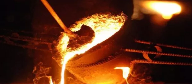
Main Causes of Drag Marks in Casting
When it comes to metal casting, drag marks most commonly occur during the mold filling or pattern withdrawal stages. At their core, these defects are the result of mechanical friction between the pattern (or part) and the mold. But the root causes go much deeper—and understanding them is critical for manufacturers aiming to deliver flawless surface quality.
Let’s explore the most common causes in detail:
Mold Wall Friction During Pattern Withdrawal
In traditional sand casting or investment casting, drag marks frequently occur when the pattern is removed from the mold. As the pattern is pulled out, friction between the mold wall and the pattern can cause:
- Material to shear away from the mold cavity
- Part of the mold surface to tear or collapse
- Surface distortion that imprints onto the final cast part
This is particularly problematic when the mold surface is:
- Not properly coated with a release agent
- Made of fine-grain sand that doesn’t bond well
- Hasn’t been compacted evenly
The deeper or more detailed the cavity, the higher the risk of drag marks forming during withdrawal.
Inadequate Draft Angle
The draft angle is the taper applied to the vertical surfaces of the pattern. If the draft angle is too shallow—or worse, nonexistent—the pattern has to be forcibly removed from the mold. This high-friction action is a prime cause of drag marks.
Common mistakes include:
- Forgetting to add draft to internal features
- Using standard angles when larger drafts are needed for coarse molds
- Applying uniform draft across complex geometry without accounting for shrinkage or mold material behavior
Adding as little as 1–2 degrees of extra draft can dramatically reduce the chance of surface damage during withdrawal.
Poor Mold Surface Preparation
A rough or improperly prepared mold surface can:
- Increase adhesion between the pattern and the mold
- Cause uneven tearing or deformation during withdrawal
- Leave textured drag patterns on the final part
In some cases, the mold surface might also develop micro-cracks or loose particles, especially in sand casting. These can be dragged across the surface of the part during metal flow or pattern removal, creating linear scratches or gouges.
The solution? Proper mold compaction, drying, and finishing are essential. A smooth and stable mold cavity is far less likely to create drag marks.
Metal Flow and Turbulence
In pressure-based casting methods like die casting, high-speed molten metal enters the mold cavity at extreme pressure. If the gating system is not properly designed, turbulent flow can:
- Displace sand or ceramic particles from the mold
- Cause splashing that erodes mold surfaces
- Trap debris between the mold wall and the flowing metal
This movement introduces irregularities into the cavity wall, which later transfer as drag marks or flow lines onto the part.
Furthermore, metal shrinkage during cooling can pull against the mold wall—especially if cooling is uneven—exacerbating surface defects.
Incorrect Mold Coating or Release Agent
Some manufacturers apply graphite, alcohol-based, or ceramic coatings to sand or permanent molds to improve part finish and release. However:
- If coating is applied unevenly
- If it’s too thick or too thin
- If the coating breaks down at temperature
… it can contribute directly to the formation of drag marks.
Over time, coating build-up or degradation can even create ridges or texture on the mold surface that gets transferred repeatedly to cast parts.
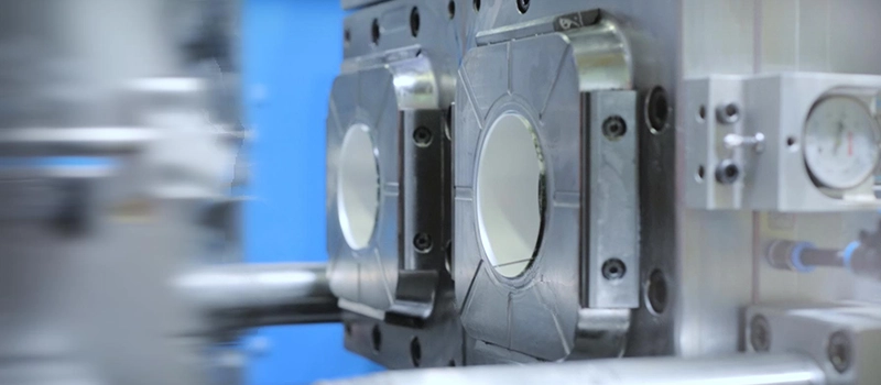
What Causes Drag Marks in Injection Molding?
While injection molding is a more controlled and repeatable process than traditional casting, drag marks are still a common and persistent defect in plastic parts manufacturing. These linear surface imperfections often run along the direction in which a part is ejected from the mold. And just like in casting, drag marks in injection molding are rooted in mechanical friction, poor mold design, or process imbalances.
Let’s dive into the core reasons drag marks appear in injection-molded parts and how manufacturers can avoid them.
Tooling Design Flaws
The mold tool design is often the first culprit behind drag marks. If the design doesn’t support smooth part ejection or clean separation from the mold cavity, friction increases—and with it, surface defects.
Common design-related causes include:
- Insufficient draft angles on vertical walls or deep cavities
- Sharp corners or narrow ribs that resist smooth release
- Overly tight tolerances between part and mold walls
- Complex geometries that “lock” the part into the mold
Even the best injection molding machine can’t compensate for a tool that doesn’t support easy ejection. That’s why design for manufacturability (DFM) is crucial from the beginning.
Ejection System Problems
Once the part has cooled and solidified, the mold opens and ejector pins push the part out. If that ejection system isn’t well-calibrated or balanced, it can cause:
- Uneven ejection force across the part surface
- Deformation or bending during release
- Parts sticking or dragging against the cavity wall
In these cases, drag marks often appear exactly where the ejection stress was highest.
Contributing factors include:
- Ejector pins placed too close to thin walls
- Inconsistent ejector pin stroke
- Undersized or worn ejector pins
- Lack of ejector pin lubrication
This is why routine maintenance and dynamic mold flow analysis are essential to avoid part damage during ejection.
Uneven Cooling and Warping
Cooling plays a significant role in the shrinkage behavior of thermoplastics. If a part cools unevenly, it can:
- Warp or distort inside the mold
- Create internal stress that resists ejection
- Cause the part to drag against the mold cavity wall
As the part distorts slightly during or after ejection, contact with the mold wall can result in a visible scratch or groove—classic drag mark behavior.
Issues that lead to uneven cooling include:
- Inconsistent cooling channel design
- Hot spots in thicker sections of the part
- Poor mold temperature regulation
Using advanced mold temperature control systems and cooling simulations can help eliminate these inconsistencies.
Mold Surface Condition and Finish
The smoothness and condition of the mold cavity surface is directly related to drag mark formation. If the surface is too rough, worn, or contaminated, friction increases significantly.
Contributors include:
- Mold surface wear over time
- Micro-pitting or corrosion on the cavity wall
- Surface residue buildup (e.g., degraded material, release agents, carbon)
This leads to higher resistance as the part exits the mold, especially on vertical surfaces, ribs, or undercuts.
A polished, well-maintained mold surface minimizes resistance and allows parts to glide out more easily—reducing drag marks almost entirely.
Material Properties and Lubrication
The type of resin used in injection molding also plays a role. Some materials, such as glass-filled nylons or PC/ABS blends, are naturally more abrasive. Others may have:
- Higher friction coefficients
- Lower mold-release properties
- Greater sensitivity to mold temperature
In these cases, drag marks can result not only from poor mold design but also from a mismatch between the resin and mold setup.
Inadequate or improper use of mold release agents can further exacerbate drag marks, especially in high-cavitation molds where cycle times are tight.
In summary, drag marks in injection molding usually point to design or process imbalances. Whether it’s tooling geometry, mold maintenance, ejection pressure, or thermal inconsistencies, each must be addressed holistically. A single overlooked detail can lead to recurring surface defects across thousands of part.
Die Casting and Drag Marks: A Special Case
Die casting operates at the intersection of high-pressure metal injection and precision tooling. It’s faster than traditional casting, more complex than injection molding, and often used for mass production of high-strength, dimensionally stable metal parts. But this speed and pressure come with a price—surface defects like drag marks are much harder to avoid.
Drag marks in die casting are often more severe than in other processes. They can appear as:
- Deep scratches
- Ripping or tearing marks
- Flow lines accompanied by surface distortion
- Heat-affected discoloration or burning near mold contact points
Let’s explore why die casting is uniquely prone to drag marks, and how manufacturers can deal with them.
High-Speed Metal Flow and Mold Erosion
In die casting, molten metal—such as aluminum, magnesium, or zinc—is injected into the die at speeds of up to 60–100 meters per second. This extreme velocity and pressure are essential for filling complex cavities before the metal solidifies.
However, this also causes:
- Turbulent metal flow that scrapes along mold surfaces
- Erosion of the cavity wall, especially near gating and parting lines
- Displacement of die lubricant or coating, reducing release quality
- Mechanical shearing of mold surfaces that creates cumulative damage
If the die surface is not hard enough, properly treated, or well-lubricated, drag marks become inevitable—especially on fine features and vertical surfaces.
Poor Thermal Management
Inconsistent die temperatures are a leading cause of drag marks in die casting. If one section of the mold is hotter or cooler than another:
- The metal may solidify unevenly
- The part may shrink asymmetrically
- The release action becomes unpredictable
This can result in:
- Parts sticking in the die
- Friction-related tearing during ejection
- Surface disruption at the cooling front
The issue becomes worse in multi-cavity molds where each cavity may behave differently. Using high-precision thermal control systems, pre-heating dies, and automated cooling cycles can reduce this risk dramatically.
Mold Coating and Release Agent Failures
Die casting relies heavily on die coatings and release agents to protect mold surfaces and ensure smooth part ejection. However, issues arise when:
- Coatings are worn or improperly applied
- Incompatible release agents are used for certain metals
- Over- or under-application causes buildup or exposure
- Environmental conditions (humidity, temperature) affect performance
When coating deteriorates or is missing in areas of high pressure, the molten metal sticks to the die surface, resulting in:
- Tearing or gouging when the part is released
- Residual buildup that damages the next shot
- Repeated drag marks in consistent locations
Routine application and inspection of coatings are non-negotiable in die casting.
Inadequate Ejection Force or Placement
Just like in injection molding, the ejection phase in die casting is critical. If ejection pins don’t apply uniform pressure or are misaligned:
- Parts may twist or deform during release
- Drag marks form at contact points or high-stress zones
- Surface features may crack or get gouged
This is particularly true in die-cast parts with complex geometry or thin walls, where even minor ejection flaws become amplified on the surface.
Proper mold design includes:
- Optimized placement of ejection pins
- Adequate ejection stroke and pressure
- Timed ejection with die opening to avoid early movement
Metal Alloy and Part Geometry Factors
Finally, not all metals behave the same. Aluminum alloys, for example, can be more prone to drag marks due to:
- High thermal expansion
- Fast solidification
- High viscosity under injection pressure
Parts with thin ribs, deep holes, or sharp corners also increase the likelihood of drag marks during ejection and cooling. The more complex the geometry, the more critical it becomes to simulate mold flow and test ejection force distribution before full production.
In summary, drag marks in die casting are a symptom of high-speed, high-pressure metal movement interacting with imperfect tooling. Managing them requires a systems approach: correct alloy selection, thermal balancing, tooling hardness, mold coatings, and predictive maintenance.
How to Identify Drag Marks Early
In manufacturing, early detection of defects like drag marks is vital. It helps prevent defective products from reaching customers, avoids costly rework, and maintains trust in quality. Fortunately, drag marks are one of the more visually identifiable surface defects—if you know where and how to look.
Let’s go through the methods factories, inspectors, and engineers use to identify drag marks before parts leave the production line.
Visual Inspection Techniques
The most common—and often most effective—way to detect drag marks is through direct visual inspection.
Here’s how professionals do it:
- Bright lighting: Inspect parts under consistent, high-contrast lighting conditions to reveal surface scratches or gouges.
- Angled viewing: Rotating or tilting the part allows shallow marks to catch the light, making them more visible.
- Magnification: Low-power magnifiers or handheld digital microscopes help reveal fine drag lines, especially on smaller components.
- Color contrast techniques: Applying a light dusting of developer powder or dye penetrant (used in surface testing) can make marks stand out.
It’s important that the personnel conducting these inspections are trained to distinguish between cosmetic blemishes and functional defects. Drag marks that occur on critical surfaces—like sealing faces, alignment features, or cosmetic zones—must be flagged for rework or rejection.
Tactile Testing
Sometimes, visual inspection isn’t enough—especially when surface finish requirements are tight. In such cases, inspectors may run gloved fingers across a part to feel for:
- Surface roughness
- Raised edges along scratch lines
- Sharp ridges or gouges
While this method is subjective, it’s widely used for quick sorting on the production floor, especially for die cast and injection molded parts.
Surface Profile Measurement Tools
When the surface quality is critical—such as in aerospace, automotive, or medical applications—quantitative tools are used to measure surface deviations caused by drag marks. These include:
- Surface profilometers: Devices that scan across the part surface to measure roughness (Ra), waviness (Wa), and peak-to-valley height (Rz).
- 3D laser scanners: These offer full-surface mapping and can identify scratch depth, length, and distribution.
- Confocal microscopy: For extremely fine inspection of molded or cast surfaces, confocal microscopes can identify defects invisible to the naked eye.
These tools provide hard data that can be compared against quality standards and client specifications.
Inline Automated Inspection Systems
For high-volume manufacturing, manual inspection isn’t scalable. That’s where automated vision inspection systems come in. These systems use:
- High-resolution cameras
- Machine learning algorithms
- Pattern recognition software
They scan each part for irregularities in surface texture, color, or shape. When drag marks are detected, the system can:
- Automatically sort defective parts
- Flag units for re-inspection
- Stop production for investigation if defect frequency increases
These systems are commonly found in injection molding plants, automotive part suppliers, and advanced die casting lines.
Inspection During Different Production Stages
A smart approach is to inspect parts for drag marks at multiple stages:
- Post-ejection: Catch immediate surface defects before they are passed down the line.
- Pre-packaging: Ensure only clean, acceptable parts are shipped.
- Random batch audits: Pull random samples hourly or per batch to statistically monitor defect rates.
This multi-stage strategy improves detection accuracy and helps trace the root cause if drag marks appear consistently.
Linking Inspection to Root Cause Analysis
It’s not enough to just detect drag marks—you must also investigate the when, where, and how they occurred. Inspection reports should track:
- Time of occurrence
- Mold cavity or machine number
- Operator shifts
- Tool maintenance history
This allows engineers to connect defects to specific molds, materials, or process conditions—and correct the problem proactively.
Identifying drag marks early is not only about quality control, but also about cost efficiency and brand reputation. Once marks are found, it’s essential to move quickly into corrective action mode, either through tooling changes, mold maintenance, or part reprocessing.
Engineering Solutions to Prevent Drag Marks
Preventing drag marks isn’t about fixing problems after they occur—it’s about eliminating the conditions that cause them in the first place. Whether you’re producing metal castings, die-cast components, or injection-molded parts, the key is to take a systematic, engineering-driven approach to part design, tooling, and processing.
Here are the most effective, proven solutions used in professional manufacturing environments to prevent drag marks before they ever appear.
Pattern and Part Design Improvements
Draft angle optimization is one of the most effective and commonly overlooked fixes. Adding appropriate draft angles reduces resistance between the part and the mold cavity wall, making it easier for the part to release cleanly.
Key design adjustments include:
- Increasing draft angles, especially in deep or narrow cavities
- Rounding internal corners to minimize material sticking
- Removing unnecessary undercuts that may cause sticking or shearing
- Designing ejection surfaces that allow even pressure distribution
In casting and injection molding, using CAD/CAM simulations during the design stage helps engineers visualize potential friction points where drag marks could form.
Gating and Flow System Adjustments
For casting, die casting, and injection molding alike, the flow of material into the mold plays a major role in surface quality.
Strategies include:
- Repositioning gates and runners to reduce turbulence
- Ensuring laminar, controlled metal or resin flow
- Adding overflow wells to catch impurities or flow irregularities
- Reducing injection pressure or fill rate to minimize mold erosion
For die casting and injection molding, software simulations of mold flow dynamics (like Moldflow or MAGMASOFT) can predict hot spots, air traps, and areas of high friction that lead to drag marks.
Mold Coating and Surface Finish
The smoother the mold or die surface, the lower the chance of drag marks.
Best practices include:
- Polishing mold cavity surfaces to the appropriate Ra value (usually Ra ≤ 0.8 µm)
- Applying die coatings (e.g., titanium nitride, chrome plating) to increase surface hardness and reduce metal-to-metal friction
- Using mold release coatings and lubricants compatible with the chosen material
- Reapplying coatings at regular maintenance intervals to prevent wear
In sand casting, the use of high-quality facing sand and anti-stick additives (like graphite or zircon) on mold surfaces also helps reduce surface friction.
Ejection System Optimization
A poorly designed ejection system is one of the most frequent causes of drag marks, especially in plastic and die-cast parts.
Engineering improvements include:
- Increasing the number of ejector pins to distribute force more evenly
- Optimizing pin size and stroke for part geometry
- Using ejector sleeves or lifters for complex shapes
- Ensuring precise alignment between the ejector plate and the mold cavity
- Adding sensors to monitor ejector pin stroke and detect anomalies
When necessary, air ejection systems or vacuum-assisted release can also help reduce part-to-cavity friction.
Cooling and Shrinkage Control
Drag marks caused by uneven cooling or differential shrinkage can be addressed by improving mold temperature regulation.
Engineering recommendations:
- Designing uniform cooling channels around critical surfaces
- Using thermal analysis tools to identify hot spots
- Pre-heating or tempering molds to reduce shrinkage gradients
- Employing cycle time controls to ensure consistent part solidification
Consistent cooling prevents warping, internal stress buildup, and friction hotspots that cause drag marks during ejection.
Material Selection and Additives
The material itself plays a role in drag mark formation. For example:
- Soft aluminum alloys may be more prone to tearing in die casting
- Glass-filled plastics can create higher friction in injection molds
- Certain sand compositions in casting may not release as cleanly
Possible solutions:
- Choosing resins or alloys with better mold release properties
- Adding internal lubricants or flow modifiers to plastic compounds
- Testing alternate sand binders or anti-stick coatings in casting molds
For each material type, ensure that the mold temperature, coating, and process settings are aligned to prevent friction-based surface damage.
Mold Maintenance and Cleaning
Even the best-designed molds will degrade over time. Regular preventive maintenance is essential to avoid the conditions that lead to drag marks.
Maintenance routines should include:
- Polishing worn cavity areas
- Removing buildup of material residue or release agent
- Checking ejector pins for wear or misalignment
- Reapplying protective coatings
- Inspecting for micro-cracks or surface pitting
A good rule of thumb: if you see drag marks in consistent locations, the mold likely needs inspection and resurfacing.
Solutions for Existing Drag Marks
Even with the best engineering practices, drag marks can still occur—especially in high-volume production where tooling wears down over time or where minor process fluctuations go unnoticed. When they do appear, manufacturers face a decision: Can the part be saved, or must it be rejected?
In this section, we’ll explore practical solutions for dealing with drag marks after production, including surface finishing techniques, repair options, and rejection criteria.
Grinding and Machining
If the drag marks are shallow and located on non-critical surfaces, light surface grinding or polishing is often the first go-to method. This is common in both casting and die casting.
Techniques include:
- Hand grinding or polishing using abrasive pads, wheels, or rotary tools
- Automated belt grinding for high-volume parts with consistent geometry
- CNC surface re-machining for precision areas where surface finish and tolerances must be restored
This method is effective for:
- Cast housings or brackets with cosmetic imperfections
- Die-cast components where dimensions allow minor surface stock removal
- Mating surfaces that require smooth contact but not ultra-precision
However, it’s important to note:
- Excessive grinding can weaken structural integrity
- It may alter part dimensions beyond tolerance
- It increases labor cost and cycle time
So while grinding is a valuable repair method, it’s not always scalable.
Shot Blasting, Sanding, and Surface Finishing
For large batches of parts with mild to moderate drag marks, surface treatments can mask or remove the defects.
Popular methods include:
- Shot blasting: Bombards parts with fine steel or ceramic media to uniformly clean the surface. Ideal for die-cast or sand-cast parts.
- Sandblasting: Uses abrasive particles to remove surface imperfections; best for non-aesthetic or structural components.
- Tumbling or vibratory finishing: Uses media and compound in a vibratory bowl or barrel. Suitable for small parts in bulk.
- Buffing and polishing: Used for decorative or functional finishes, especially in aluminum or stainless-steel parts.
These methods can:
- Improve cosmetic appearance
- Prepare surfaces for painting or coating
- Reduce the visibility of light drag marks
But they don’t fix deep gouges or dimensional defects caused by serious friction during ejection.
Surface Coating and Painting
In some cases, surface drag marks can be hidden or protected using industrial coatings such as:
- Powder coating
- Anodizing (for aluminum)
- Zinc plating
- Liquid paint with filler primers
Coatings can mask fine surface scratches and improve corrosion resistance, especially in non-critical components. However:
- They cannot correct structural or functional drag mark damage
- Coatings may exaggerate underlying texture if not properly prepared
So coating is best used in conjunction with mechanical repair—not as a standalone fix.
Rework vs. Rejection Criteria
Every manufacturer must define clear criteria for when a part with drag marks should be:
- Reworked
- Accepted “as is”
- Scrapped and replaced
These decisions depend on:
- Location of the drag mark (cosmetic vs. functional)
- Depth and length of the scratch or gouge
- Surface roughness specification (Ra or Rz values)
- Part tolerance limits
- End-use application (e.g., sealing surface, load-bearing area, visual zone)
If drag marks:
- Affect a sealing face → Reject or remachine
- Appear in non-visible areas → Polish or coat
- Alter part dimensions → Re-machine if cost-effective, otherwise scrap
Establishing these rules helps prevent inconsistent decision-making and ensures product quality meets customer expectations.
Cost Considerations
Before attempting any rework, it’s essential to evaluate:
- Cost of labor vs. cost of scrap
- Time impact on delivery
- Risk of part failure post-repair
- Customer specification limits
In some industries—especially medical, aerospace, or automotive—repaired parts may not be allowed due to strict certification requirements. In such cases, any part with drag marks in critical zones must be rejected outright.
Conclusion
Drag marks may look like minor surface issues, but in casting, die casting, and injection molding, they signal deeper problems with tooling, process control, or mold design. If left unaddressed, these defects can lead to part rejection, costly rework, and even product failure.
By understanding what causes drag marks, how to detect them early, and how to prevent them through engineering controls, material choices, and routine maintenance, manufacturers can ensure smoother production, higher part quality, and stronger customer satisfaction.
Consistent quality begins with attention to detail—and drag marks are a detail that should never be ignored.