Undercut machining often seems harmless in a CAD model, but becomes a real challenge once the part hits the shop floor. The geometry looks simple—until a tool can’t reach it.
Suddenly, what looked like a clean shoulder or relief groove demands custom tooling, altered toolpaths, or extra setups. When features are missed during planning, they slow production, drive up cost, and create avoidable scrap.
Recognizing undercuts early makes them easier to handle. With the right approach, it’s possible to maintain precision without redesigns or late-stage surprises.
What Is Undercut Machining?
Geometric Definition
Undercut machining refers to the removal of material in recessed areas that are not accessible by standard straight-line tool paths. An undercut is typically defined as a feature that cannot be reached using a conventional end mill or turning tool due to obstruction from adjacent geometry—such as walls, shoulders, or internal features.
In CAD, an undercut is not always obvious until tool orientation and access paths are evaluated. These features are often hidden below overhangs, inside grooves, behind bosses, or beneath threads. As a result, they present challenges in programming, tool selection, and inspection.
Where Undercuts Occur
Undercuts are most common in these situations:
- Turned parts: Relief grooves at thread ends, internal O-ring grooves, or shaft steps
- Molded parts: Snap fits, side-locking features, and core pin geometries
- Milled parts: Pockets with inward-facing ledges, keyways behind support walls
- Cast components: Cooling passages and trapped cores that require post-processing
These features often arise from functional design needs such as clearance, locking, or sealing. While they may serve a purpose, they introduce geometric complexity that requires special machining consideration.
Why They’re Problematic
The difficulty with undercut machining lies in tool access and process planning. Standard cutting tools—such as square or ball end mills—cannot reach beneath a ledge or behind a wall. Attempting to machine these features without the proper tool leads to incomplete geometry, tool collision, or deflection.
Furthermore, undercuts often exist in areas where chip evacuation is poor. This increases the chance of re-cutting chips, tool wear, or surface damage. In automated CNC workflows, any geometry requiring non-standard access must be flagged early, or it will trigger production delays, reprogramming, or tooling redesign.
From a quality standpoint, undercuts can be hard to measure. If the feature is internal or partially obscured, traditional metrology tools may not reach it. This makes first article inspection more difficult and increases the risk of undetected dimensional errors.
Summary of Key Characteristics
- Undercuts are not visible from a simple top-down or planar view
- They require special tools or multi-axis strategies to machine
- Their location often interferes with standard fixture or probe paths
- If overlooked during design, they lead to costly downstream corrections
Common Types of Undercuts
Internal vs. External Undercuts
In undercut machining, the first distinction lies in whether the feature exists inside a part cavity or on its external surface.
- Internal undercuts are found inside bores, cavities, or hollow sections. Common examples include internal grooves for snap rings, thread reliefs, and sealing channels. These features cannot be accessed by standard axial tools without interference from surrounding walls.
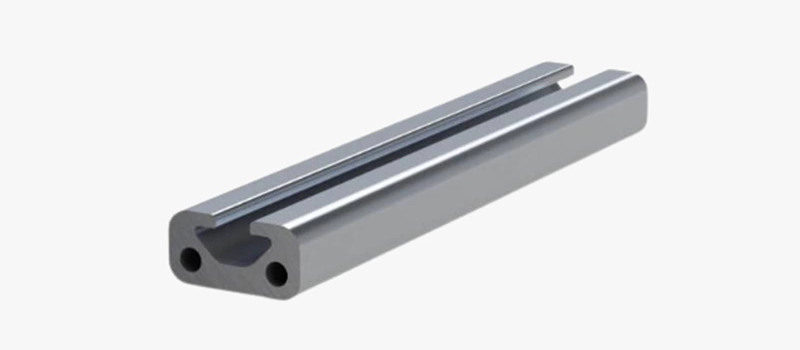
- External undercuts appear on the outer surface of a component, such as relief grooves on shafts or slots beneath external overhangs. These are more accessible, but they still require precise radial tool positioning and often custom form tools to generate the correct profile.
The difference affects not only tool accessibility but also how parts are fixtured and inspected. Internal features usually require long-reach or offset tools, while external features may demand rotary alignment or angled tool engagement.
Axial and Radial Undercuts
Undercuts also vary based on the direction of approach required to machine them:
- Axial undercuts are those that cannot be reached from the top or along the spindle axis. These often occur in lathe parts where a shoulder or thread obstructs tool access. For example, a groove behind a threaded section cannot be formed with a basic turning tool.
- Radial undercuts involve features that are blocked from the side or along the part’s circumference. These occur in milled pockets, corners, or around flanges. Machining them typically requires T-slot cutters, lollipop tools, or 5-axis motion to reposition the part.
Each case presents different challenges for tool geometry, fixturing, and toolpath programming. Misidentifying an undercut’s orientation can result in incomplete machining or tool collisions.

Thread Reliefs and Groove Features
One of the most common and often overlooked types of undercut is the thread relief groove. These grooves provide clearance for tap exit or thread termination in turned parts. If omitted, the thread form may run into an uncut shoulder, creating assembly problems or damaged mating threads.
Sealing grooves—such as O-ring channels—are another typical example. These require undercut machining because their geometry sits below the surrounding surface and cannot be formed with a standard tool path. They often involve precise width and depth control to maintain sealing integrity.
Snap-fit or locking grooves in plastic or molded parts are also undercuts by nature. While often formed in molding, post-machining is needed in metal equivalents where mechanical undercuts are cut into a sidewall or slot.
Multi-Surface and Compound Undercuts
In complex parts, undercuts may occur across more than one surface or axis. For example:
- An internal cavity may have a recessed groove that wraps around two sides of the wall
- A pocket may feature both axial and radial obstruction, requiring compound movement
- A cast or forged feature may trap geometry that must be cleared with EDM or 5-axis machining
These situations require specialized planning and custom tooling. If not addressed early, they result in machining interruptions, additional setups, or design revisions.
Causes and Design Drivers
Functional Geometry Requirements
Undercuts often originate from legitimate functional needs in the part’s design. One of the most common drivers is clearance—particularly in assemblies that require thread relief, snap-fit retention, or sealing grooves. When a mating part must fully seat without obstruction, an undercut provides space for threads to terminate cleanly or for seals to compress properly.
In mechanical interfaces, undercuts allow for locking features or shoulders to engage without affecting other surfaces. For example, grooves behind threads or shaft steps enable better clamping or press-fit behavior without forcing tolerances to tighten unnecessarily across the entire part.
These are not decorative features—they are built-in allowances that protect functional zones from interference. Ignoring them during early design often leads to part rejection, assembly issues, or over-constrained tolerances.
Tool Accessibility Constraints
In many designs, the root cause of undercut machining is limited tool access due to surrounding geometry. For example, a part may require a groove or profile that lies underneath an overhanging section or behind a perpendicular wall. The resulting geometry blocks direct tool paths and forces the use of form tools, extended reach cutters, or multi-axis positioning.
These constraints are rarely visible in 2D technical drawings but become immediately apparent during CAM setup or simulation. Without early detection, they lead to unexpected tooling revisions, changes in approach strategy, or complete reprogramming of toolpaths.
As component complexity increases, particularly in die-cast, forged, or molded parts, access limitations naturally give rise to internal or compound undercuts.
Assembly Considerations
Another frequent source of undercut features is the need to support downstream assembly. For example, when a part includes snap-in or twist-lock elements, undercuts allow for the flexible deformation or mechanical interlock needed to assemble or disassemble the system without damaging either component.
Undercuts also appear in parts that are joined using adhesive, where recessed areas help contain overflow without interfering with mating surfaces. In hydraulic and pneumatic assemblies, small internal grooves act as flow paths or containment zones for seals and rings.
These design elements serve mechanical, fluid, or motion purposes and are not optional from a functional standpoint. However, they complicate tool access and dimensional control—factors that must be communicated clearly during DFM review.
Tolerance Relief and Manufacturing Flexibility
In some cases, undercuts are introduced to avoid the need for ultra-tight tolerances elsewhere. By isolating a critical fit area with an undercut, designers can relax tolerances in non-functional zones. This approach improves manufacturing yield, especially in high-volume production where maintaining narrow tolerances across the entire part would be cost-prohibitive.
For example, a shaft may have a small relief groove behind a bearing seat to ensure full contact and prevent shoulder interference. In such cases, the undercut reduces risk without increasing part complexity—provided it is machined correctly.
Machining Methods for Undercuts
CNC Turning with Grooving Tools
In undercut machining on lathes, grooving tools are the most direct solution. These tools are designed with narrow widths and extended necks to reach behind shoulders, threads, or steps that block standard turning tools. In axial undercut machining, the tool enters parallel to the spindle axis and removes material at the base of a feature.
Tool rigidity is critical. Because undercut machining often requires long overhangs, cutting forces concentrate at the tool tip. Excessive depth or feed causes deflection, chatter, or tool breakage. For this reason, undercut machining on turned parts typically uses conservative cutting parameters and multiple passes.
Thread relief grooves are a common example. If undercut machining is not applied correctly, the thread form runs into the shoulder, causing assembly interference. In production environments, this type of undercut machining is standardized, but only when tool geometry and approach angles are clearly defined.
Milling with Form and Lollipop Tools
In milling operations, undercut machining is usually performed using form cutters, T-slot cutters, or lollipop-style end mills. These tools allow material removal beneath an overhanging feature where standard end mills cannot reach.
Lollipop tools are especially common in undercut machining for mold cavities and complex pockets. Their spherical cutting head enables radial engagement below a ledge while maintaining clearance for the shank. However, because only a small portion of the tool contacts the material, cutting forces are uneven, and surface finish depends heavily on toolpath control.
Undercut machining with milling tools requires precise CAM programming. Entry paths, exit paths, and step-over distances must be controlled to avoid tool rubbing or sudden load spikes. Any programming error in undercut machining increases the risk of tool collision due to limited visual access during cutting.
Multi-Axis Machining Strategies
Five-axis machining expands the options for undercut machining by allowing the tool or part to tilt. Instead of forcing a specialized tool into a restricted space, the machine reorients the workpiece so that the undercut becomes accessible with a standard cutter.
This approach reduces tool overhang and improves surface quality. However, undercut machining in multi-axis setups introduces its own challenges. Machine kinematics, rotary accuracy, and collision avoidance become critical. Small angular errors can translate into dimensional deviations at the undercut location.
Because of these risks, undercut machining in five-axis systems is typically reserved for high-value parts where precision outweighs cycle time and programming cost.
EDM for Inaccessible Undercuts
When mechanical cutting cannot reach a feature, electrical discharge machining becomes an alternative. Wire EDM and sinker EDM are both used for undercut machining in hardened materials or enclosed geometries.
EDM-based undercut machining removes material without cutting forces, eliminating deflection risk. This makes it suitable for deep internal undercuts or sharp internal corners. However, EDM is slow, expensive, and limited by electrode or wire access.
As a result, EDM is rarely the first choice for undercut machining. It is used when geometry, hardness, or accessibility makes conventional machining impractical.
Method Selection Considerations
Choosing the right undercut machining method depends on several factors:
- Feature location and accessibility
- Material hardness and heat treatment state
- Required surface finish and tolerance
- Production volume and cost limits
In many cases, undercut machining is not a single operation but a sequence of roughing, finishing, and inspection steps. Early identification of undercut features allows engineers to select the least risky method instead of forcing complex solutions late in production.
Tooling and Setup Risks in Undercut Machining
Tool Deflection and Vibration
One of the most critical risks in undercut machining is tool deflection. Because the tool must often reach deep into confined areas—such as behind shoulders or beneath overhangs—the cutting length-to-diameter ratio increases. This creates a highly flexible tool system, especially when using grooving tools or lollipop cutters.
Even minor radial cutting forces can cause the tool to bend away from the cut surface. In undercut machining, this deflection reduces dimensional accuracy, affects surface finish, and introduces variability between parts. If the deflection exceeds tool clearance, it may also cause the tool to drag along walls, increasing heat and wear.
Vibration is another related concern. As the tool extends farther from the holder, system rigidity decreases. Interrupted cuts, entry points, or overly aggressive feeds can excite resonance. Once vibration begins during undercut machining, it is difficult to suppress without modifying speed, depth, or tool geometry.
Limited Chip Evacuation
Undercut machining often occurs in recessed or enclosed geometries. These spaces restrict chip flow, particularly when the tool is moving horizontally or radially. Chips have limited escape paths and tend to accumulate in the cavity.
Recutting of chips becomes a serious concern. When chips are re-engaged by the tool, they can score the finished surface, reduce tool life, and generate heat. In tight internal undercuts, chips can compact into the groove, causing tool jamming or even breakage.
Coolant delivery is also compromised. Because tool access is already limited, direct coolant flow may not reach the cutting zone effectively. This leads to thermal load buildup, which accelerates wear and disturbs dimensional control. Undercut machining with poor chip evacuation always results in inconsistent quality.
Clearance and Fixturing Issues
Undercut machining demands careful attention to fixturing. Since the feature to be machined is often hidden or recessed, the part must be oriented so that the tool has unimpeded access. Poor fixturing introduces several risks:
- Insufficient clearance between tool and clamp hardware
- Toolholder collisions with adjacent geometry
- Fixtured part vibration during extended tool contact
- Inability to verify tool position visually during the operation
These problems are especially critical in CNC environments where dry runs may not reveal interference within the undercut region. In complex parts, fixture design must consider tool swing radius and full travel path to ensure safe, complete material removal.
Tool Compatibility and Limitations
Undercut machining relies on specialized tools, many of which are non-standard or custom ground. Common tools such as undercut grooving inserts or lollipop end mills are available in limited diameters and lengths. If the undercut feature requires a non-standard geometry, tool modification becomes necessary.
Incorrect tool choice leads to:
- Partial feature generation
- Interference with neighboring geometry
- Premature tool wear due to incorrect contact angle
Additionally, many undercut machining tools have low rigidity and limited coating options. Their unique geometry restricts toolholder compatibility, meaning shops must verify that spindle extensions, collet types, and drawbar systems match the tool spec.
Programming Errors and Setup Inconsistency
Setup errors in undercut machining often originate in the CAM environment. Because undercuts are hidden from direct view, simulation must confirm that toolpaths respect part boundaries and that cutter orientation avoids collision.
Typical setup mistakes include:
- Incorrect start or retract position
- Feedrate too high for extended tool length
- Missed undercut regions due to projection errors
- Overlapping passes causing ridge buildup
When undercut machining is repeated across multiple parts or setups, consistency becomes a challenge. Any deviation in Z-zero location, angular orientation, or tool length offset can cause the undercut to shift outside of spec. Unlike open cuts, undercut errors are difficult to detect visually without sectioning or indirect metrology.
Conclusion
Undercut machining introduces real complexity into otherwise routine manufacturing processes. Its challenges—tool access, fixturing, chip evacuation, and dimensional control—require early recognition and deliberate planning. With the right methods and tools, undercut features can be produced reliably, but ignoring their constraints leads to instability, cost overruns, and downstream failures.