Why do structural beams twist under eccentric load? Why do some fail under localized bending while others carry massive spans effortlessly? Why does the same “steel” behave so differently depending on its shape?
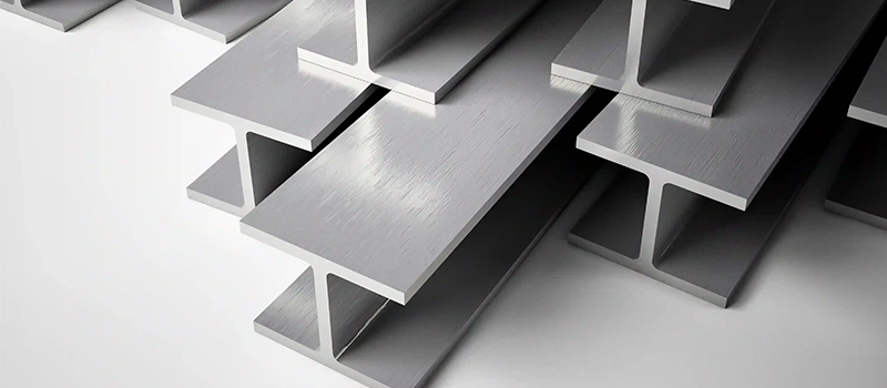
As Eurocode 3 (EN 1993-1-1) states, “The geometry of the cross-section has a significant influence on the resistance to bending, shear, torsion and local buckling.” In other words, shape matters. Steel beam types—W, S, C, T—are not interchangeable. Each has specific load paths, torsional limits, and fabrication constraints that must be understood before application.
Misusing beam types in design or procurement leads to premature failure, poor field fit-up, or unnecessary cost. Selecting the right profile starts with understanding the differences.
What Defines Steel Beam Types?
Terminology Basics: Flanges, Web, Neutral Axis
Every steel beam type is defined by three structural components: flanges, web, and the neutral axis. The web resists shear forces, while the flanges carry bending stress. Between them lies the neutral axis, where internal forces change direction. These elements determine how the beam distributes load and how it must be supported.
Load Transfer Through Cross-Section
The geometry of each section governs how forces pass through it. In a W beam, the wide flanges provide strong bending resistance. In contrast, C beams concentrate force along one plane, increasing torsional risk. Shape alone, not just material, dictates structural efficiency.
Importance of Symmetry in Stability
Symmetry improves predictability. W and S beams, being symmetric about both axes, perform well under balanced loading. Asymmetric profiles like C and T beams are prone to twisting or warping unless braced correctly. This has major implications in real-world assemblies and welding setups.
Key Metrics: Section Modulus, Moment of Inertia
Two metrics dominate beam selection: section modulus and moment of inertia. Section modulus controls resistance to bending. Moment of inertia governs deflection under load. These vary dramatically across steel beam types, even when outer dimensions appear similar.
Bending Resistance vs. Depth
A W10×30 and an S10×30 beam may share depth, but their bending resistance differs. The W beam offers higher section modulus due to uniform flange width. This is critical when designing for long spans or point loading. Incorrect assumptions can result in mid-span sag or vibration.
Rotation, Deflection, and Shear Behavior
Beams with higher inertia resist bending but may not resist shear. S beams, with their tapered flanges, have less web area near supports, leading to localized web shear. Design engineers must factor in both global behavior and support zone weakness.
Influence of Geometry on Structural Behavior
Beam geometry influences not just strength, but failure mode. A wider flange increases bending resistance but reduces torsional stiffness. A deeper web handles shear but increases lateral instability. This is why beam selection cannot be based on load alone.
Axis Strength and Buckling Risk
W beams handle strong-axis loading efficiently. But under minor-axis bending, even a strong profile can buckle if unbraced. T beams especially lack lateral support due to missing compression flanges. Geometry drives not only capacity, but how the beam fails.
Fabrication Compatibility and Cut Loss
Wider flanges mean more surface for welding, but also more distortion risk. Tighter radius flanges in S beams limit access during fabrication. C beams are easier to cut but harder to align. The geometric profile affects labor, accuracy, and even waste in cutting tables.
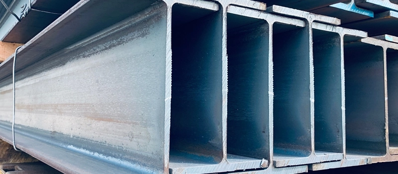
W Beams (Wide Flange Beams)
Properties and Strength Characteristics
Among all steel beam types, W beams offer the highest efficiency in resisting flexural loads across long spans. Their design includes wide, parallel flanges with consistent thickness, contributing to a uniform stress distribution. The symmetry of W beams around both axes allows them to perform reliably under bending, axial, and combined loads.
Flange Width and Moment Capacity
The wide flanges increase the section modulus, making W beams the preferred choice when span-to-depth ratio or lateral stability is a concern. They resist lateral-torsional buckling better than narrower profiles. For this reason, many structural engineers favor W shapes in both roof beams and transfer girders.
Axis Balance and Load Uniformity
W shapes behave predictably under strong-axis bending. The uniform flange geometry reduces torsional warping and simplifies end connection detailing. This makes them well-suited for bolted and welded fabrication processes, especially where multidirectional loads are involved.
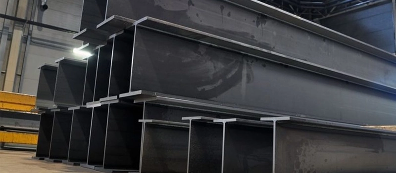
Best Use Cases: Building Frames, Bridges, Columns
W beams dominate in high-load steel beam types used for framing in commercial and industrial construction. Their high section capacity makes them ideal for both primary and secondary structural members. In bridge design, they offer reliable performance under both static and dynamic loads. In vertical applications, W columns handle compression with minimal lateral bracing.
Long-Span Roof Beams
The geometry of W beams enables extended spans without intermediate supports. This is advantageous in warehouses, aircraft hangars, and open-floor plan buildings where support placement is limited.
Heavily Loaded Vertical Members
In multistory construction, W beams are used in stacked columns due to their consistent axial load resistance and alignment compatibility with beam flanges in moment-resisting frames.
Manufacturing Considerations: Rolling and Fabrication Limits
Not all steel beam types are equally fabricable. W beams are typically hot-rolled under controlled dimensional tolerances. Their broad flanges allow greater weld area, but also require attention to distortion during heat exposure. Overwelding can introduce residual stresses and flange bowing, especially in thinner sections.
Availability in High-Strength Grades
Most W beams are produced in ASTM A992 steel, offering consistent yield strength, weldability, and dimensional control. Some regions also provide W shapes in dual-certified grades, allowing them to meet EN 10025 requirements for international projects.
Welding and Flange Distortion Risk
The flange surface, while useful for connections, becomes vulnerable to heat-induced warping. During fabrication, tack welding and symmetric sequencing are required to prevent flange pull or web deviation. This must be considered during CNC layout and jig preparation.
Where W Beams May Fail: Torsion, Buckling Without Bracing
Despite their advantages, W beams are not immune to failure. Among steel beam types, they are especially sensitive to lateral-torsional buckling if left unsupported over long spans. Without continuous lateral bracing, their top flange under compression may deflect, especially under eccentric or impact loads.
Lateral Torsional Buckling
When W beams span long distances without restraint, the compression flange becomes unstable. This leads to lateral movement and twist, often resulting in structural underperformance or failure. Design codes such as AISC and EN 1993 impose strict limits on unbraced lengths for this reason.
Poor Performance in Cantilevered Loads
In cantilevered conditions, W beams require additional flange reinforcement or moment connections. Their standard geometry is not optimized for high torsional moments without secondary bracing systems, such as torsion boxes or diaphragms.
S Beams (American Standard Beams)
Differences from W Beams: Tapered Flanges
Within common steel beam types, S beams stand out for their tapered flanges. Unlike W beams, which have flat and parallel flanges, S beams are curved and narrow toward the edge. This difference affects both load behavior and fabrication. The shape limits flange contact area, influencing weld continuity and bolt alignment.
Uneven Stress Flow
Tapered flanges change how bending stress flows through the section. Stress tends to concentrate near the web-to-flange junction, leading to localized strain zones. This makes S beams less efficient than other steel beam types when used under full-span bending conditions.
Limitations in Compression Members
S beams perform poorly in compression compared to symmetric W sections. Their reduced flange area contributes to premature flange local buckling under axial load. For columns or transfer members, W or box sections are preferred.
Load Behavior: Local Instability, Bending Resistance
Steel beam types with non-parallel flanges introduce geometric weaknesses. S beams are especially prone to local instability near supports, where load transfer peaks. The flange curvature reduces rotational restraint, making the section less stable under eccentric or shifting loads.
Shear Flow Along Tapered Flanges
Shear transfer is disrupted by the non-uniform flange geometry. In bolted connections, washers and shims are often required to level the bearing surface. Welds must be extended beyond standard locations to prevent tearing at the curved junction.
Reduced Moment Capacity
Among standard steel beam types, S beams offer the lowest moment capacity per unit weight. Their slender flanges and deeper web reduce bending efficiency. They may still be suitable in short-span applications but offer minimal value for long unsupported lengths.
Manufacturing Impact: Handling and Welding Risks
From a production standpoint, S beams require additional care in handling and fit-up. The flange shape complicates clamping during automated welding. Misalignment is more likely, especially where multiple sections must be joined on-site.
Fit-Up Challenges at Web-Flange Junction
The tight radius at the web-flange intersection creates interference with standard welding nozzles and positioning tools. This affects both robotic and manual processes. Among steel beam types, S profiles often require specialized jigs or staged welding to reduce distortion.
Practical Limits: Field Fit Issues, Connection Problems
Steel beam types with curved or irregular profiles increase the risk of poor connection alignment. S beams are no exception. In field conditions, tolerances are tighter, and minor misalignment can prevent bolt insertion or cause flange tilt during welding.
Difficulty in Bolted End Connections
Standard end plates often assume parallel flanges. With S beams, adjustments are needed to match the tapered shape. This adds labor time and can compromise structural integrity if not properly addressed.
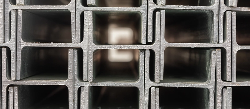
C Beams (Channels)
Use in Secondary Framing and Load Transfer
C beams are one of the most misunderstood steel beam types in structural and framing applications. Their open, asymmetrical geometry limits their role in primary load-bearing systems. Instead, C beams are more appropriate for secondary structures such as purlins, side rails, equipment platforms, and wall studs. Their ease of access makes them attractive, but their structural behavior imposes serious constraints.
Light Framing and Non-Critical Support
Steel beam types with open profiles like C channels are often used in framing systems where load is predictable and light. Their geometry supports cladding, grating, or secondary members, but not critical axial or moment-bearing applications.
Torsional Weakness and Load Eccentricity Risk
Among all steel beam types, C beams are the most torsion-sensitive. Their open section lacks symmetry, making them vulnerable to twisting under point loads, especially when the load is applied off-center. This is a major design concern in seismic or dynamic load environments.

Twisting Under Axial or Point Load
The single web and one-sided flange alignment cause rotation about the vertical axis under eccentric loading. This torsional instability may lead to crack propagation at bolted joints or misalignment at floor decking connections.
Common Misuse in Structural Applications
Despite being widely available, C beams are often overused or misused due to their simplicity. In many cases, engineers mistakenly substitute C channels for other steel beam types without adjusting load paths or checking deflection limits.
False Assumptions of Symmetry
Designers sometimes assume a channel behaves similarly to a W beam when oriented vertically. This is incorrect. The asymmetry introduces secondary bending and deflection. Under repeated loading, C beams are more prone to fatigue cracking at stress risers, particularly at bracing points or near weld terminations.
Fabrication and Joining: Warping, Bracing Needs
From a fabrication perspective, C beams are simple to cut but complex to assemble in structural frames. Their open profile requires additional bracing and lateral restraint, increasing the overall cost and time of field installation. Compared to other steel beam types, the structural preparation for C beams can outweigh their initial material savings.
Welding Requires Careful Restraint
Welding across the web can introduce localized warping due to the unbalanced cross-section. Pre-positioning with fixtures is necessary to avoid flange spreading or twisting during cooling. Heat input must be minimized, particularly near bolted connections or gusset plates.
Extra Bracing to Prevent Lateral Deflection
Because C beams lack a compression flange on one side, lateral bracing becomes mandatory over long spans. This adds weight and coordination effort. In seismic zones or tall vertical members, improper bracing can result in lateral instability failures during load reversals.
T Beams (T-Sections)
Cut From W Beams or Rolled Separately
T beams are one of the less frequently applied steel beam types, typically produced by cutting a W beam longitudinally through the web or by rolling a T-profile directly. This creates an open, asymmetrical shape with no opposing flange, severely limiting its structural symmetry and bending capacity.
Asymmetrical Behavior
The removal of one flange causes T beams to lose strong-axis symmetry. This makes them susceptible to twisting and uneven deflection, particularly under any eccentric or fluctuating loading. Unlike other steel beam types, T sections are inherently unbalanced and should be handled as such in both design and fabrication.
Lateral Instability and Load Distribution Limits
Among all steel beam types, T beams have the lowest lateral stability due to the absence of a compression flange. When installed horizontally, the top flange is unsupported along one edge. This causes warping under bending loads and increases the demand for lateral bracing or continuous decking support.
Strong-Axis vs. Weak-Axis Load Risks
Although a T beam still maintains strong-axis bending strength from its remaining flange and web, the lack of a second flange reduces torsional resistance. When subjected to off-center or rotational forces, the beam may twist or experience local buckling far earlier than symmetric steel beam types.
Welding and Fit-Up Challenges
Fabricators must treat T beams differently than W or S sections. The single flange offers less surface area for connection. The sharp transition from flange to web is more prone to heat-induced distortion during welding, especially if not clamped or restrained properly.
Heat-Affected Zone at Cut Edges
When T beams are produced by sawing a W section, the cut edges often require grinding or dressing to remove stress risers. These areas are highly sensitive to weld cracking and fatigue initiation, especially when subjected to cyclical loading or vibration.
Restricted Use in Modern Design Codes
T beams are rarely listed in standardized load tables. Most modern structural codes discourage their use for primary members due to poor performance under torsion and low bending efficiency. Among all steel beam types, T sections are most often confined to architectural framing, infill members, or non-critical supports.
Limited Standard Span Tables
Designers working with T beams typically require custom load calculations. Standardized charts for span, load, and deflection are unavailable or unreliable due to the shape’s asymmetry. This increases design time and raises the risk of misapplication in field conditions.
Beam Type Selection: Key Criteria
Span Requirements vs. Beam Depth
Span-to-depth ratio is a primary factor in selecting from available steel beam types. Longer spans demand deeper sections to limit mid-span deflection. However, increasing depth impacts fabrication, shipping, and headroom in building design. W beams often provide the best balance between span efficiency and manageable profile size.
Depth-to-Span Efficiency
For typical floor systems, a depth-to-span ratio of 1:20 is a common guideline. W beams offer favorable section modulus for their weight, reducing the number of required intermediate supports. In contrast, C and T beams are rarely used where long spans are needed due to inadequate stiffness and lateral stability.
Torsion and Lateral Support
Steel beam types vary widely in their torsional behavior. W and S beams perform well when laterally braced and loaded through the shear center. C and T beams, with their open profiles, require frequent bracing or diaphragm integration to maintain alignment under live load conditions.
Need for Bracing in Slender Sections
In unbraced conditions, slender beams are vulnerable to lateral-torsional buckling. Design codes prescribe maximum unbraced lengths for various steel beam types, often requiring continuous decking, bridging, or secondary members to stabilize top flanges in compression zones.
Field Assembly, Welding, and Tolerance Fit
Selection of steel beam types must also account for field conditions. Beam-to-column connections, flange alignment, and bolt-hole tolerances affect construction speed and long-term performance. Flange geometry determines fit-up behavior, especially in skewed or offset framing.
Section Uniformity and Cut Loss
W beams, with their flat, wide flanges, simplify fabrication and cut planning. Less time is spent adjusting fixtures or trimming distorted ends. S and C beams introduce complexity in welding and bolting, especially when dealing with field cuts or rework. Cut loss is also greater for asymmetrical profiles due to positioning difficulty on automated cutting lines.
Cost-Efficiency vs. Risk in Long-Term Use
While material cost is a factor, selecting steel beam types purely on weight or price can introduce structural risk. Long-term performance, vibration control, and fatigue life are influenced more by geometry and placement than by unit price alone.
Failure Cost vs. Initial Material Savings
Underestimating flange width, torsional rigidity, or bracing requirements can lead to service failures, excessive deflection, or retrofitting costs. A slightly more expensive beam that eliminates a row of columns or reduces installation complexity can yield a more efficient project lifecycle.
Conclusion
Steel beam types are not interchangeable. Geometry controls strength, behavior, and risk. Choosing the correct type—W, S, C, or T—depends on span, load, and fabrication method. Misuse leads to instability, poor fit, or failure. Understanding the structural role of each section supports safer, more efficient design.