Why do some castings fail to meet dimensional tolerances even when the alloy and process remain unchanged? Why do surface defects like misruns or shrinkage appear despite best efforts in pouring and cooling? Often, the root cause lies not in the metal — but in the mold cavity.
As noted by the American Foundry Society, “Proper mold design — especially cavity geometry and flow paths — is essential for achieving cast components with minimal defects and maximum dimensional accuracy.” In other words, even small flaws in mold cavity structure can directly lead to costly production issues and part failures.
Understanding the role of the mold cavity in casting is key to improving part quality and consistency. From wall thickness transitions to draft angles and thermal balance, every detail in cavity design matters. In this article, I’ll break down how mold cavity structure influences casting outcomes — and what you can do to optimize it.
What Is a Mold Cavity in Casting Production?
Understanding the Mold Cavity in Real-World Casting
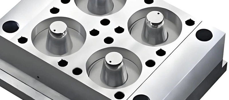
In the context of metal casting, a mold cavity is the hollow negative space that defines the shape of the final part. It’s more than just an empty void — it’s a precision-engineered form that determines the geometry, surface finish, and dimensional accuracy of the casting. Mold cavities are at the center of every casting process and must be aligned with production goals, material properties, and tool capabilities.
Mold Cavity Formation in Different Casting Methods
Sand casting
In sand casting, mold cavities are formed by packing molding sand around a reusable pattern. Once the pattern is removed, the cavity left behind serves as the space for molten metal. This method allows flexibility in cavity design and is widely used for large or complex components.
Die casting
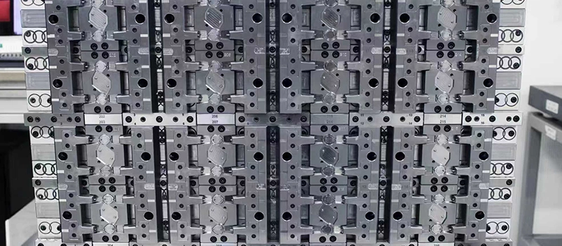
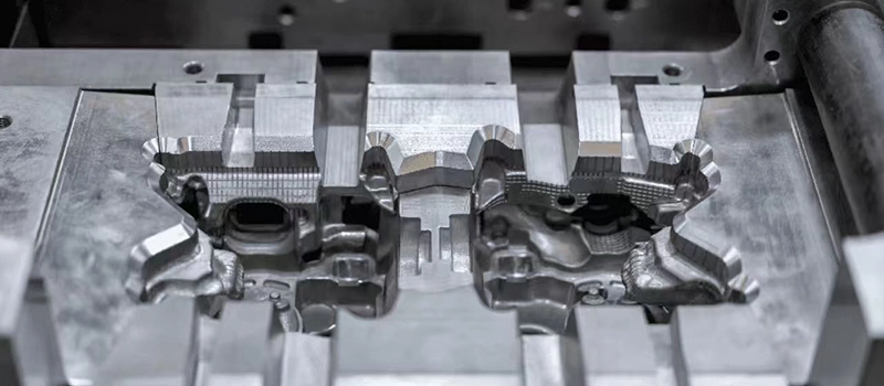
Die casting relies on steel dies where the mold cavity is CNC-machined into tool steel. This process is used for high-volume production and requires excellent dimensional consistency. The cavity must be designed to withstand repeated injections of molten metal under pressure.
Investment casting
For more intricate shapes, investment casting uses wax patterns and ceramic shells. The mold cavity here is created once the wax melts out during the burnout stage. The resulting cavity offers exceptional detail and is ideal for precision components.
Mold Cavity Within the Larger Mold System
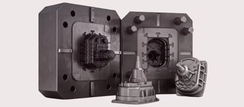
The cavity doesn’t function alone — it is integrated with other parts of the mold system including runners, sprues, gates, and cores. These features guide molten metal into the cavity and help control the flow, fill rate, and cooling behavior. If the cavity is poorly designed or mismatched with the gating system, defects like misruns, cold shuts, or turbulence may occur.
Use of Cores and Multi-Part Cavities
Many castings require cores to create hollow features or internal passages. These are placed within the mold cavity and must align precisely to maintain dimensional integrity. Cores can be sand-based or metallic, and their fit within the cavity is critical — even slight misalignments can cause wall thickness variations or flow restrictions.
Key Mold Cavity Features That Affect Part Quality
Wall Thickness and Mass Distribution
The importance of thermal balance
Uniform wall thickness in a mold cavity is essential to prevent uneven cooling, internal stresses, and shrinkage defects. In real production, cast parts with varying wall thicknesses often experience hot spots or cold shuts — areas where molten metal cools too fast or too slowly.
Managing different section sizes
To ensure consistent metal flow and solidification, mold cavities are typically designed to maintain a balanced thermal profile. Thinner sections must be fed quickly, while thicker areas may need chill zones or risers to control cooling. Poorly managed wall thickness often leads to internal porosity or distortion, increasing rejection rates and costs.
Fillets, Radii, and Sharp Corners
Reducing turbulence during flow
Internal fillets and radii help direct molten metal smoothly and minimize turbulent flow. Sharp corners, by contrast, act as stress risers, which can lead to cracking, air entrapment, or incomplete fills — especially at the intersection of complex geometries.
Extending mold tool life
Smooth transitions also reduce mechanical stress on mold tooling, especially in die casting. In production settings, tooling with poor radii design tends to wear faster and requires more frequent maintenance or replacement.
Draft Angles and Part Removal
Preventing part sticking
Draft angles are essential for releasing the casting from the mold without damaging its surface or the cavity. A vertical wall without draft causes friction and can trap the part, especially in precision dies or tight-core sand molds.
Typical angle ranges
Depending on the casting method and material, typical draft angles range from 1° to 3°. In die casting, where part ejection is automated, even a small reduction in draft can lead to mechanical failures and reduced throughput.
Surface Texture Zones in the Cavity
Controlling final surface quality
The condition of the cavity’s internal surface defines the texture of the finished casting. In sand casting, this depends on the grain size and binder. In die casting, it’s influenced by cavity polishing, coating, or texturing.
Reducing post-processing costs
Maintaining a controlled and consistent surface texture inside the cavity can minimize or even eliminate the need for secondary polishing or machining. This is especially important for parts with cosmetic or sealing surfaces.
Mold Cavity Behavior During Pouring and Cooling
How Molten Metal Moves Through the Mold Cavity
Flow starts with gating and cavity entry
When molten metal enters the mold cavity, its initial movement is driven by gravity, pressure, or both — depending on the casting process. The cavity’s geometry determines how the metal spreads, fills internal spaces, and maintains consistent velocity. Uneven shapes or abrupt changes in section thickness can cause flow separation, leading to misruns or air entrapment.
Cavity design affects flow direction and turbulence
In real-world casting, sharp turns, flat planes, or bottlenecks in the mold cavity often result in turbulence or splashing. These disrupt flow and introduce oxide films or bubbles that can’t easily escape. A smooth, continuous cavity layout helps molten metal fill all regions uniformly.
Cavity Cooling Behavior and Solidification Timing
Wall thickness dictates cooling rate
As molten metal fills the cavity, solidification begins at the mold walls and moves inward. Thinner sections cool and solidify faster, while thicker areas remain liquid longer. Poorly designed cavities may cool unevenly, creating internal stress or shrinkage cavities in slower-cooling regions.
Controlling solidification through cavity shape
To prevent defects like centerline shrinkage or hot tears, mold cavity geometry must promote directional solidification — encouraging metal to freeze from the farthest point toward the riser or gating system. Tapered walls and progressive section transitions are common design features that assist in this.
Defect Risks During Pouring and Cooling
Cold shuts and misruns from poor cavity layout
Cold shuts occur when two fronts of molten metal meet and fail to fuse due to low temperature or improper flow. These defects are often traced back to long, narrow cavity sections or obstructed paths where metal cools before fully filling the area.
Shrinkage and porosity from thermal imbalance
Shrinkage voids form when metal solidifies without adequate feed from a riser or surrounding liquid. If the cavity doesn’t allow for smooth feeding, internal porosity or collapse can occur. Thermal simulations are often used in foundries to test and correct these risks before production.
Adjusting Mold Cavity Design for Different Casting Methods
Differences Between Sand Casting and Die Casting Cavities
Sand casting allows for flexible geometry
In sand casting, the mold cavity is created using compressible sand around a pattern. This allows for considerable design freedom and easy modification of cavity features. Complex geometries, variable wall thicknesses, and large sizes can be achieved without expensive tooling changes.
However, due to the granular nature of sand, the surface finish from the cavity is relatively coarse. Shrinkage and dimensional variation are more likely, requiring careful allowance in cavity dimensions. Draft angles in sand molds must be larger to compensate for sand fragility during pattern withdrawal.
Die casting requires high precision and draft control
In die casting, the mold cavity is machined into steel dies, which are closed and held under high pressure during metal injection. Cavity design must account for thermal expansion, metal velocity, and ejection force. Because die cavities are used in high-volume production, their geometry must be extremely consistent and durable.
Die cast cavities also require tighter tolerances and more precise draft angles, typically smaller than in sand casting. Every corner, boss, or fillet must be precisely machined and often surface-treated to ensure release and longevity.
Investment Casting and Mold Cavity Complexity
Ceramic molds enable high-detail cavity reproduction
Investment casting uses wax patterns and ceramic shells to create mold cavities that can capture extreme detail. This allows for thin walls, intricate geometries, and near-net-shape castings. However, once the ceramic shell is formed, no modification can be made, so the cavity design must be perfect before production.
Wall thickness and shrink compensation
Cavity shrinkage allowances in investment casting are critical. Since the ceramic shell has low thermal conductivity, the cavity cools the metal slowly. Therefore, the mold cavity must account for both casting shrinkage and wax pattern shrinkage to maintain dimensional accuracy.
Tooling Considerations and Mold Lifespan
Metal vs. sand cavity tooling
Cavity design in metal molds (like die casting) prioritizes tool life, requiring hardened steel inserts and attention to wear zones. In sand casting, where molds are discarded after each use, cavity tooling focuses more on pattern durability than long-term wear.
Complexity drives cavity segmentation
For large or geometrically complex castings, cavities are often segmented into multiple parts using cores, inserts, or collapsible tooling. The need for multi-part cavities is dictated by undercuts, hollow features, or post-processing access, and the approach differs based on the casting method.
Common Production Issues Traced to Mold Cavity Problems
How Poor Mold Cavity Design Leads to Defects
Misruns and incomplete filling
One of the most common production issues tied to mold cavity problems is the misrun. This occurs when molten metal cools before fully filling the mold cavity. In many cases, the root cause is traced back to narrow sections, abrupt transitions, or dead-end zones in the cavity geometry. These regions slow the flow and promote early solidification.
If the mold cavity does not encourage smooth, continuous flow, especially in large or complex parts, metal may stall mid-fill, leading to thin walls, weak joints, or open cavities in the final product. These flaws increase scrap rates and damage production timelines.
Cold shuts from poor flow path design
Cold shuts result when two separate flows of molten metal meet inside the mold cavity but fail to fuse properly due to low temperature or turbulence. This often happens when the cavity layout forces metal to split and reconverge without controlled direction.
A well-designed mold cavity ensures metal flows from one origin point, avoiding unnecessary divisions or thin channels. Rounded corners, gradual transitions, and even wall thickness all help prevent cold shut formation in high-volume casting.
Shrinkage Defects and Internal Porosity
Uneven cooling causes internal stress
Another frequent casting defect related to mold cavity design is shrinkage — either as surface cavities or internal porosity. Poorly distributed wall thickness within the mold cavity leads to thermal imbalance. Thick regions cool slower, while thinner walls freeze first, trapping liquid metal and gases inside.
A practical solution used in foundries is to shape the mold cavity for directional solidification, allowing metal to freeze from the farthest point toward the riser or feeding system. When cavity geometry does not support this, shrinkage cavities and voids are more likely.
Lack of venting or air escape paths
While not part of the mold cavity itself, air escape routes are designed around the cavity. If the cavity design traps gases during pouring, those gases form pinholes, blisters, or other porosity problems. Venting and overflow channels should be integrated into the cavity layout during tooling design.
Warping, Distortion, and Surface Irregularities
Dimensional deviation from cavity stress points
Some castings emerge from the mold with unexpected bends or warps. This is often due to internal stresses caused by uneven solidification — another effect of mold cavity design. Features like unsupported overhangs, sharp corners, or thick bosses freeze slower and shrink unevenly.
When designing the mold cavity, attention to mass balance and stress concentration is essential. Reinforcing ribs or gradual transitions can be built into the cavity itself to maintain shape and reduce post-cast straightening or machining.
Practical Guidelines for Improving Mold Cavity Performance
Start with Simulation and Digital Modeling
Use casting simulation software to test mold cavity design
Before physical tooling is made, advanced simulation software like MAGMASOFT, ProCAST, or FLOW-3D can model how molten metal flows through the mold cavity. These tools help engineers visualize potential misruns, cold shuts, and shrinkage zones — long before any metal is poured.
By running multiple cavity shape scenarios digitally, foundry teams can identify weak points in geometry, optimize flow paths, and make real-time adjustments to wall thickness or gating layout. Simulation is now considered a standard step in mold cavity design for high-value or complex parts.
Validate geometry against production constraints
Simulation also allows the mold cavity design to be checked against real constraints — like cycle time, fill temperature, and pouring speed. These digital models can then be refined and exported directly to CNC machining centers or pattern shops for tooling fabrication.
Collaborate Across Teams from Day One
Involve casting, tooling, and machining teams early
A common issue in many production environments is late-stage changes to the mold cavity due to overlooked details. To prevent this, mold cavity design should be a joint task between the casting engineer, toolmaker, and downstream machinist.
Each team brings a different perspective: casting engineers focus on flow and solidification; toolmakers prioritize manufacturability; machinists highlight post-processing limitations. When all voices are included early, the resulting mold cavity is more likely to meet performance, quality, and cost goals.
Use Feedback Loops and Prototyping
Start small with test molds or low-run tools
Before scaling to full production, many foundries test mold cavity performance using pilot runs or small-batch tooling. These test castings reveal issues with fill, cooling, or dimensional control that might not appear in simulations alone.
Adjustments to cavity depth, draft, surface texture, or venting are common at this stage. This iterative approach helps lock in the best mold cavity geometry before major investment is made in hardened dies or large patterns.
Track cavity-related issues over time
Even after production starts, foundries should track mold cavity performance through quality control metrics. If defects increase over time, they can often be traced to cavity wear, corrosion, or subtle tooling shifts. Routine inspections and tool maintenance keep the cavity performing as designed.
Conclusion
The mold cavity is more than just a hollow shape—it’s the foundation of casting quality. From metal flow to solidification, every aspect of cavity design impacts the final part. By applying practical design principles, using simulation tools, and involving cross-functional teams early, manufacturers can greatly reduce defects and improve efficiency. A well-designed mold cavity is not just good engineering—it’s good production.