Knurling is often misunderstood as a surface-level feature, when in fact it’s a precise forming operation. Despite being common on tools, fasteners, and control components, many engineers underestimate how knurling affects function, form, and assembly performance.
When the process is poorly defined, problems follow—uneven patterns, double tracking, crushed edges, or improper fit. These defects are not just cosmetic. They can interfere with torque transfer, reduce grip reliability, or cause dimensional misalignment in mating parts.
This article breaks down the knurling process into its essential components: types of knurling, pattern design, tool selection, and how different setups behave in machining. Understanding these variables ensures consistency, prevents defects, and makes knurling a deliberate, controlled process—not an afterthought.
Knurling Basics
What Is Knurling?
Knurling is a metal forming process used to create patterned ridges or grooves on the surface of a cylindrical part. The process is typically performed on a lathe using hardened rollers or cutting tools that emboss or cut the desired texture. Unlike machining methods that remove material, standard knurling is a cold-forming operation—it displaces material plastically without reducing overall diameter.
Knurling is most commonly applied to improve grip on hand-operated parts like knobs, tool handles, and fasteners. However, its use also extends into functional applications such as press-fit mating, torque transmission, and alignment locking. In high-tolerance parts, knurling ensures consistent friction and repeatability across components.
The pattern generated is not random. It must match the part diameter, tool pitch, and rotation speed to avoid double-tracking or distortion. A proper knurling setup maintains both radial and axial force balance, ensuring uniform surface geometry. Knurling must be calculated—not guessed—especially in automated production environments.
Cold Forming vs. Cutting Knurling
There are two primary methods of knurling: forming and cutting.
Forming knurling, the most common type, uses hardened rollers to press patterns into the workpiece surface. It requires ductile materials like aluminum, brass, or mild steel. Forming generates high radial force, which can deform thinner walls or cause concentricity issues if the stock lacks rigidity. It does not generate chips and is fast in production settings.
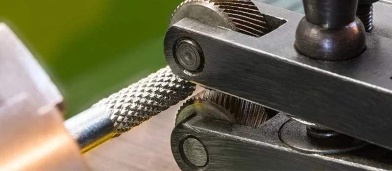
Cut knurling uses a sharp-edged tool to carve the pattern into harder or more brittle materials. This method is used when forming would result in surface tearing or tool wear. Cut knurling requires precise feed control, slower speeds, and results in material removal rather than displacement.
Both methods demand proper tool alignment, feed rate, and surface preparation. The wrong approach can create distorted knurls, leading to part rejection or rework.
Primary Functions of Knurling
Knurling serves three main functions:
- Grip enhancement: Improves hand or tool engagement without adding additional geometry.
- Press-fit interface: Adds surface resistance for mating parts, especially when tolerances allow minor interference.
- Visual or branding purpose: Offers a decorative finish or consistent surface identity in consumer-facing components.
Knurling Processes Explained
Roll Knurling
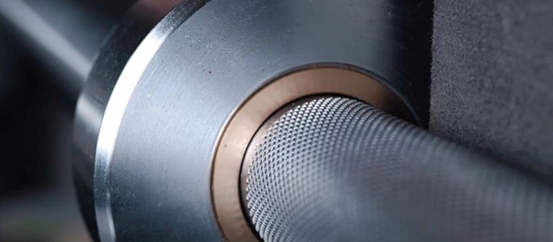
Roll knurling is the most widely used process in industrial settings. It relies on a hardened wheel or die with a pre-formed pattern. As the wheel contacts the rotating workpiece, high radial force displaces surface material into the die’s cavities, forming a consistent raised texture.
This is a cold-forming process, meaning no material is removed. Instead, the metal flows into the knurl tool geometry. It works best on ductile metals such as aluminum, brass, and mild steel. Because there are no chips, it offers cleaner operation and faster cycle times than cutting methods.
Tool selection depends on pitch, pattern type, and pressure requirements. Equally important is tool center alignment. Any angular deviation results in tracking errors or tapered patterns. Roll knurling also introduces axial load into the spindle and can distort thin-wall tubing if not supported properly.
Roll knurling is suited for:
- High-volume production
- Parts requiring cosmetic finish
- Hand-operated components needing better grip
Cut Knurling
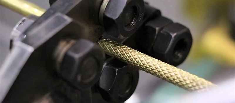
Cut knurling removes material using a sharp, V-shaped tool. It’s typically used on hard metals or alloys where forming would cause surface tearing or excessive stress. The tool is fed into the workpiece at a precise angle and with low radial force. This avoids distortion but generates chips that must be cleared.
Unlike forming, cut knurling demands tight control of feed rate and rotational speed. Too slow, and the pattern will overlap. Too fast, and the tool may skid or skip tracking. Pattern pitch must be matched to the part’s circumference to avoid double tracking.
Cut knurling is preferred when:
- The workpiece material is hard or brittle (e.g., stainless steel, tool steel)
- A sharp-edged, high-contrast pattern is required
- Tool load must be minimized (e.g., thin-walled parts or small-diameter shafts)
While slower than forming, cut knurling provides high precision and can be used in tight tolerance environments.
Manual vs. CNC Knurling
Manual knurling uses lathe-mounted tools operated by machinists. Success depends on operator skill—especially in controlling pressure, speed, and feed rate. Manual processes are prone to inconsistencies but offer flexibility for prototypes or one-off jobs.
CNC knurling, by contrast, allows tight control over all process variables. Parameters like RPM, tool pressure, depth, and feed rate are programmable. CNC also supports automated pattern indexing, repeatable outcomes, and integration with multi-step operations.
CNC knurling is ideal for:
- Repeat production with dimensional control
- Tight tolerances on pattern depth and spacing
- Machining in harder materials with defined tool paths
Process Behavior Under Load
The performance of a knurling operation changes significantly with load conditions:
- Too much radial force: causes material tearing, crushed edges, or loss of roundness
- Too little force: results in shallow, uneven patterns or incomplete texture
- Unstable feed or inconsistent RPM: introduces pattern drift, double tracking, or chatter
Types of Knurling Patterns
Straight Pattern
The straight pattern is characterized by vertical lines running parallel to the workpiece axis. This design is often selected for components requiring linear engagement, such as sliding adjustments or axial grip applications.
Its geometry provides directional resistance, making it useful for parts that are pulled or pushed along their length. However, it does not offer rotational grip. That makes it unsuitable for knobs or handles requiring twist control.
Straight patterns are easy to align and produce. They place less stress on the tool and workpiece compared to more complex geometries. Their simplicity also reduces the chance of tracking errors in manual operations.
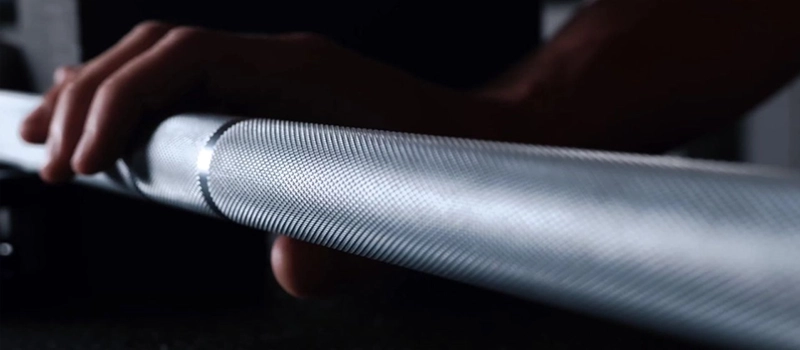
Diamond Pattern
The diamond pattern is the most common and versatile. It features intersecting diagonal lines that form raised, diamond-shaped pyramids across the surface. This geometry enhances grip in multiple directions and is ideal for parts operated by hand, such as instrument knobs or screw heads.
The aggressive texture generated by this pattern increases tactile feedback. It also improves performance in oily or dirty environments where slip is a concern. For aesthetic parts, the diamond pattern provides a clean, uniform appearance.
This pattern requires precise alignment and force control. Misalignment can cause double-tracking, where the pattern fails to repeat properly along the surface. CNC systems are often preferred for diamond knurling to maintain uniformity.

Helical Pattern
Helical knurling consists of angled lines that follow a continuous spiral around the workpiece. It is less common in general-purpose applications but valuable in specific mechanical functions.
This pattern can help guide mating components during insertion, such as in self-tapping bushings or interference-fit assemblies. The angled ridges create a rotational lead-in effect that aids in alignment.
Helical patterns must be carefully coordinated with feed rate and spindle rotation. Because the pattern relies on continuous advancement, any feed variation can distort the spiral.
Custom or Hybrid Patterns
Some advanced applications use customized geometries that combine elements of the above types. These may include partial knurling zones, alternating pitches, or crosshatch modifications tailored to specific handling or branding needs.
For example, medical tools may require soft-touch grip zones formed with lower-profile knurls, while fasteners may include aggressive textures only at the point of engagement.
Creating hybrid patterns requires specialized tooling and programmable control. These designs are typically applied in industries such as aerospace, defense, or high-end consumer goods, where function and form must coexist precisely.
Knurling Tools and Setup Considerations
Tool Types
The tools used for surface texturing vary based on method and machine type. The most common include:
- Knurling wheels: These are hardened steel rollers with a fixed pitch and pattern engraved into the surface. They are mounted on holders that apply radial or tangential pressure. Rollers are used for forming operations and come in different diameters, pitches, and pattern angles.
- Cutting knurl tools: Unlike rollers, cutting tools feature sharp edges designed to remove material rather than deform it. They are typically single-point or twin-wheel assemblies and are used in applications where the material is too hard or brittle for forming.
- Knurling holders: These devices provide the structure and clamping required to keep the tool aligned during the process. For twin-wheel tools, the holder ensures balanced force distribution, reducing lateral stress on the part.
Tool selection should match the material type, diameter of the part, and pattern requirements. Overly aggressive tools can damage workpieces or produce inconsistent patterns.
Setup on Manual Lathes
In manual operations, setup plays a decisive role in pattern accuracy. Operators must align the tool perpendicular to the part’s axis and select feed rates that match the tool’s pitch. Failure to do so often results in double tracking—a common defect caused by pitch mismatch between tool and part rotation.
Recommended practices include:
- Centering the tool accurately to avoid tapered patterns
- Using steady rests or supports for long, slender parts
- Applying consistent coolant or lubricant to reduce tool wear
Even with experienced machinists, slight misalignment or excessive tool pressure can distort the final result.
Setup in CNC Systems
CNC machines offer a significant advantage through parameter control and repeatability. Knurling tools mounted on live tooling stations or gang-style setups can be programmed with precise RPM, depth, and feed rates. This reduces human error and improves consistency across production batches.
In multi-axis setups, knurling can be integrated into part programs that include turning, grooving, and facing. This eliminates repositioning and improves cycle efficiency.
However, not all CNC systems are optimized for knurling. Excessive radial force from forming may exceed axis torque limits or introduce harmonic vibrations. Careful consideration of toolpath sequencing, dwell time, and cutting loads is essential.
Tool Wear and Inspection
Over time, knurling tools degrade. Signs of wear include:
- Rounded or chipped teeth on the knurling wheel
- Inconsistent pattern depth
- Material smearing or flattening instead of raised ridges
Regular inspection and replacement schedules are critical in high-volume production. Worn tools not only compromise part quality but can introduce vibration or surface damage to the spindle assembly.
Visual inspection, magnification, and simple pattern comparators are effective for detecting early wear before tool failure occurs.
Application Limits and Common Failures
Material Limitations
Not all metals respond well to surface patterning. Forming-based knurling depends heavily on material ductility. If the material is too brittle—like hardened tool steels or certain cast alloys—it may crack or tear under pressure. Conversely, overly soft materials such as pure aluminum can deform excessively, leading to smeared or flattened patterns.
Cutting tools extend the application range but come with their own limits. High-strength alloys like Inconel or hardened stainless steels can wear down cutting edges rapidly and require rigid setups. Surface finish and hardness must be considered before applying any knurling process.
Material grain structure also plays a role. Inhomogeneous or directionally forged stock may cause irregular flow during forming, distorting the pattern or shifting alignment over the part’s length.
Thin Wall and Small Diameter Risks
Parts with thin walls or small diameters are particularly sensitive to the radial forces involved in forming. The pressure from knurling wheels can collapse tubes, distort roundness, or induce waviness along the axis. Without internal support or back pressure, these parts are often unsuitable for traditional forming methods.
For such cases, cutting tools offer reduced radial load—but at the cost of increased cycle time and tool complexity. Some shops opt to pre-machine grip textures instead, avoiding knurling altogether.
Pattern Defects
Common pattern failures include:
- Double tracking: Occurs when the pitch of the tool and the circumference of the part do not align. This causes overlapping or ghost patterns.
- Underforming: Caused by insufficient pressure or tool wear, resulting in shallow ridges.
- Overcompression: Excessive pressure that flattens or smears the pattern, especially in soft materials.
- Tracking drift: Misalignment that creates angled or offset patterns inconsistent across the part.
These failures often originate from improper setup, tool mismatch, or ignoring pitch compatibility. Once formed, knurled defects are nearly impossible to recover without re-machining or scrapping the part.
Machining Integration Issues
When the knurling operation is performed after other finishing steps, problems can arise:
- Surface contamination: Oils or films left from prior processes may affect material displacement.
- Dimensional interference: Knurling increases the diameter locally. If downstream fits or coatings are applied without compensation, interference or tolerance issues may occur.
- Interrupted patterns: Parts with grooves, steps, or varying diameters may break the continuity of the knurl. This limits its function in gripping or seating.
To avoid these issues, knurling should be integrated early in the machining sequence or factored into the part’s dimensional stack-up.
Equipment and Setup Errors
Even with the right material and tools, setup errors introduce failure risk:
- Tool angle not perpendicular to part axis
- Excessive or insufficient feed rate
- Lack of coolant leading to work hardening or thermal distortion
- Machine vibration causing chatter in the pattern
Proper documentation of setup parameters, combined with routine inspection, helps prevent these avoidable errors in both manual and CNC environments.
Industry Use Cases and Selection Criteria
Common Industry Applications
Knurling is a well-established feature across industries where manual interaction, mechanical interference, or surface contact stability is critical. While often considered a secondary operation, it serves core functional purposes in high-precision components.
- Automotive: Applied on control knobs, shafts, and press-fit bushings. Knurled sections ensure grip, alignment, and resistance to rotation in static assemblies. It is also used in lightweight pedal systems and manual adjustment parts.
- Medical Devices: For surgical tools, implants, and handheld instruments, precise tactile feedback and anti-slip surfaces are essential. Knurling is applied to instrument grips and adjustment dials using finely controlled micro-patterns to meet hygiene and ergonomic standards.
- Aerospace: In low-weight fastening systems or control handles, consistent tactile feel under extreme conditions is key. Materials must often be high strength and temperature-resistant, requiring custom knurling with tightly controlled process variables.
- Consumer Electronics: High-end headphone jacks, camera lenses, or control wheels use decorative knurls that double as grip surfaces. Aesthetics are crucial, so diamond and straight patterns with uniform pitch are preferred.
- Tool Manufacturing: Pliers, screwdrivers, and torque tools rely heavily on functional grip zones. These parts undergo repetitive mechanical stress, making knurl depth and pattern pitch essential to avoid premature wear or discomfort.
Selection Criteria by Application
When selecting the appropriate knurling process or pattern, several parameters must align with the part function:
- Functionality vs. Appearance: If grip is the main objective, a deep, coarse pattern is preferred. For visual appeal, a fine diamond pattern with polished edges may be more appropriate.
- Material Compatibility: Soft metals like brass or aluminum work well with forming; harder alloys need cutting tools. The choice directly impacts cycle time, tool life, and part integrity.
- Production Volume: High-volume production favors roll knurling for its speed and simplicity. Low-run parts or prototypes may benefit from manual or CNC cut knurling for flexibility and customization.
- Tolerance Requirements: If the knurled area interfaces with mating components, precise control of pattern depth and diameter increase is critical. This often necessitates pre-compensation in design or additional finishing operations post-knurling.
- Machine Constraints: Not all machines handle the radial loads or programming complexity of advanced knurling. Shops must ensure their equipment supports the selected process, especially in multi-axis or automated lines.
Cross-Industry Standard References
Several standards guide pattern pitch, tool geometry, and inspection:
- DIN 82: Specifies standard patterns (A, R, B) and pitch classes for knurling tools in Europe.
- ANSI B94.6: U.S. standard covering dimensional control, pitch designations, and tolerances.
- ISO 13402: Used in medical device manufacturing for handheld tools, ensuring safety and usability through standardized texture quality.
Understanding these frameworks helps engineers integrate knurling confidently into the design stage, reducing rework and manufacturing conflict.
Conclusion
Knurling remains a precise, function-driven surface process essential across multiple industries. Whether for grip, fit, or tactile feedback, its effectiveness depends on proper tool selection, material compatibility, and machine control. Misuse or poor setup can lead to critical failure, but when applied correctly, knurling offers unmatched reliability and repeatability in metalworking.