Chamfer vs fillet — this seemingly simple design choice can make or break the performance of your metal components.
Have you ever selected one without considering its impact on stress distribution, assembly fit, or part durability?
When designing for machining, bending, or casting, the edge treatment isn’t just a finishing touch — it’s a mechanical decision that matters.
As highlighted in Machinery’s Handbook, “A fillet is generally preferred over a sharp corner due to its ability to distribute stress and reduce fatigue failure.”
In contrast, chamfers are widely applied to improve assembly alignment or simplify tooling access.
Choosing incorrectly between chamfer vs fillet can lead to premature failure, poor fit, or inefficient production.
Understanding the functional differences, applications, and mechanical behavior of chamfer vs fillet is essential for any engineer or product designer working with metal parts.
In this guide, I’ll break down their key distinctions and show you exactly when and why to use one over the other.
Understanding Chamfer vs Fillet
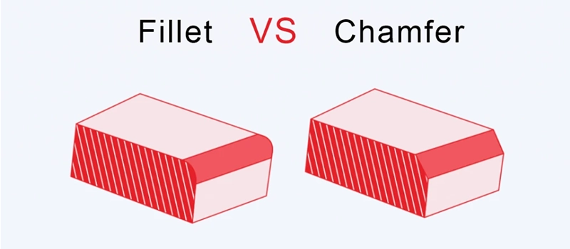
In the world of metal part design and manufacturing, chamfer vs fillet are two of the most common edge treatments. While they may seem like minor geometric features, their differences play a significant role in functionality, strength, and manufacturability.
🔹 What Is a Chamfer?
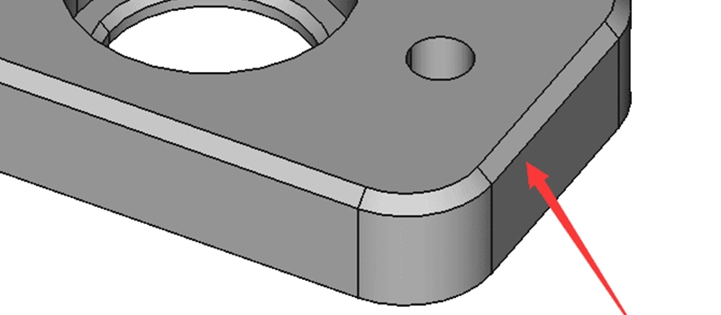
A chamfer is a beveled edge that replaces a 90-degree corner with a flat surface, typically set at a 45-degree angle. Chamfers are linear and angular by nature, serving both functional and aesthetic purposes in mechanical components. They are commonly applied to:
- Remove sharp edges for safety and handling
- Guide parts during assembly or insertion
- Improve toolpath access during machining
- Reduce minor stress concentrations at edge intersections
Chamfers are especially useful in components that require frequent assembly, such as threaded holes, shaft ends, or parts used in jigs and fixtures. Their flat geometry makes them easier and faster to machine using common CNC tools, like end mills or chamfer tools.
🔹 What Is a Fillet?
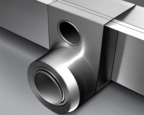
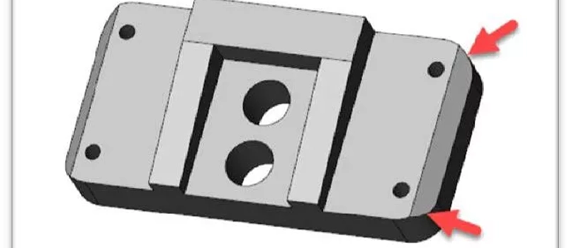
A fillet is a rounded internal or external corner that smooths the transition between two intersecting surfaces. Rather than cutting off the edge, fillets use a curve—defined by a specific radius—to blend surfaces gradually. Fillets are widely used to:
- Minimize stress concentrations, particularly in load-bearing areas
- Improve fatigue resistance in cyclic loading conditions
- Facilitate smoother material flow during casting or injection molding
- Enhance visual appeal and streamline design aesthetics
According to Design of Machine Elements, “Fillets are essential at the junctions of loaded members to prevent crack initiation due to cyclic loading.” This makes fillets a critical design element in high-performance, long-life components—especially in automotive, aerospace, and heavy equipment applications.
🔹 Geometry Comparison: Chamfer vs Fillet
| Feature | Chamfer | Fillet |
|---|---|---|
| Geometry | Straight, angled cut | Rounded, curved transition |
| Stress Distribution | Moderate, localized stress | Excellent, even stress flow |
| Machining Complexity | Simple and fast | Slightly more complex, radius-based |
| Use in Assembly | Helps with alignment and insertion | Typically no alignment function |
| Visual Appearance | Sharp, technical | Smooth, refined |
| Typical Tools | Chamfer mill, end mill | Ball end mill, form tool |
This fundamental geometric distinction explains why chamfers are often found in precision-machined parts requiring fit and clearance, while fillets dominate in structural designs focused on stress reduction and long-term durability.
Key Differences Between Chamfer vs Fillet
When it comes to choosing the right edge treatment in metal part design, chamfer vs fillet is not just a matter of preference — it’s a matter of purpose. Both techniques serve specific roles, and understanding their key differences will help you make smarter, performance-driven decisions in design, machining, and assembly.
🔹 Geometry: Angle vs Curve
The most fundamental difference lies in geometry. A chamfer replaces a sharp 90° edge with a straight-angled bevel, typically at 45°. It’s linear, angular, and defined by either length or angle. In contrast, a fillet replaces a corner with a smooth, concave radius — a curved surface that blends two intersecting planes.
This geometric variation impacts more than just appearance — it changes how the part interacts with stress, tools, and mating components. Chamfers create a precise, clean break; fillets create a gradual, seamless flow.
🔹 Stress Management
In terms of stress concentration, fillets are almost always superior. The curved geometry distributes loads more evenly and eliminates sharp transitions that often become failure points under cyclic stress. This is why fillets are standard in structural and load-bearing components, especially those under fatigue loading.
Chamfers, on the other hand, do little to redistribute stress. While they can reduce minor stress risers from sharp edges, they don’t provide the same level of reinforcement as fillets. In a chamfer vs fillet stress analysis, fillets consistently show better performance for long-term durability.
🔹 Function in Assembly
Chamfers shine in assembly-focused applications. They guide fasteners, align pins, and help components fit together more easily — especially when tolerances are tight or manual assembly is involved. For example, the entrance to a threaded hole is often chamfered to help screws engage smoothly.
Fillets don’t offer the same alignment advantages. Their strength is in internal transitions and structural reinforcement, not in guiding components during installation.
🔹 Manufacturing Considerations
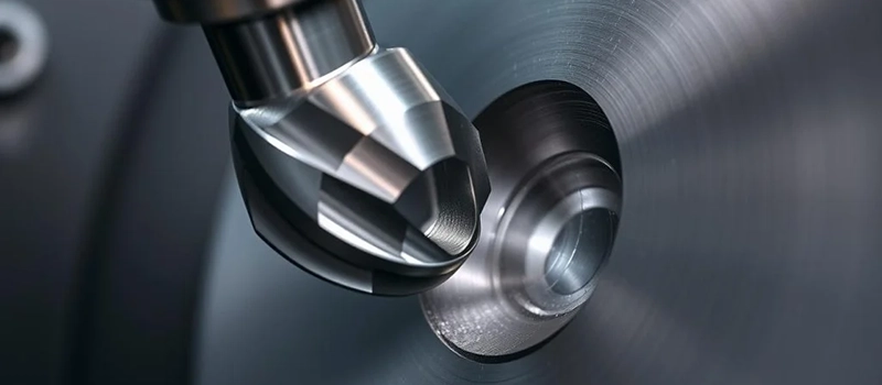
From a manufacturing standpoint, chamfers are easier and faster to machine. A single pass with a chamfer tool or end mill can create a clean bevel. Fillets, especially with small radii or internal corners, require ball-end mills, form tools, or more complex CAM programming.
This often makes fillets more expensive to produce — but in the context of chamfer vs fillet, the right choice isn’t about cost alone. It’s about matching form to function.
🔹 Aesthetic and Visual Impact
Designers also weigh aesthetics when deciding between chamfer vs fillet. Chamfers produce sharp, technical edges, which are often preferred in industrial or mechanical product designs. Fillets give a softer, more polished look, and are favored in consumer goods, medical equipment, and anything requiring ergonomic surfaces.
Advantages of Using Chamfers
In many machining and design scenarios, choosing a chamfer over a fillet offers several distinct advantages. While the chamfer vs fillet debate often centers on stress and strength, there are many use cases where chamfers are not only suitable—they’re superior.
🔹 Faster and Simpler to Machine
One of the most significant advantages of chamfers is ease of manufacturing. Creating a chamfer typically requires a single, straightforward pass with a chamfer mill, countersink, or lathe tool. There’s no need for complex toolpaths or radius tools, which saves both time and setup cost.
In high-volume production environments, this simplicity translates into real efficiency. For example, CNC programmers often prefer chamfers in parts where speed and repeatability are crucial.
🛠️ Chamfers = lower cycle time + less tool wear.
🔹 Improved Assembly and Mating
Chamfers play a critical role in guiding and aligning parts during assembly. A beveled edge can help pins, bolts, rods, or shafts enter mating holes more easily—especially in tight-tolerance fits. This is particularly important in automated or blind assembly processes where misalignment is costly.
You’ll often see chamfers around:
- Threaded hole entries
- Shaft or axle ends
- Edges of mechanical couplings
- Housing covers and alignment slots
In these cases, fillets simply can’t serve the same function.
🔹 Deburring and Safety
Sharp, unfinished corners can cause injuries, scratches, or interfere with the handling of parts. Chamfering these edges not only makes parts safer to touch but also helps reduce burr formation, especially in materials like aluminum or brass.
Compared to rounding every edge with a fillet (which requires more tool passes), applying a small chamfer is a quick and effective way to clean up a part for end-use or inspection.
🔹 Ideal for Hard, Brittle Materials
In brittle materials—such as cast iron, glass-filled plastics, or certain ceramics—a sharp internal corner can lead to stress risers and cracking. However, filleting these corners may not always be practical or machinable. In these cases, a small chamfer can help reduce edge stress without requiring complex tooling.
🔹 Consistent Appearance in Precision Machining
In precision mechanical products like gears, bushings, and tool holders, chamfers offer a clean, professional aesthetic that aligns with the functional design of the part. Unlike fillets, which appear softer and organic, chamfers convey a precise and technical look favored in industrial equipment.
Advantages of Using Fillets
In any mechanical design where durability, stress distribution, and long-term performance matter, fillets often outperform chamfers. While the chamfer vs fillet comparison depends on context, fillets are widely preferred in structural components and fatigue-prone applications for good reason.
🔹 Superior Stress Distribution
One of the most critical advantages in the chamfer vs fillet debate is how each handles stress. Fillets, with their smooth curved transitions, reduce localized stress concentrations that typically occur at sharp edges or abrupt directional changes.
By blending intersecting surfaces with a radius, fillets:
- Minimize crack initiation points
- Improve fatigue resistance under cyclic loading
- Allow smoother stress flow through the part geometry
According to Shigley’s Mechanical Engineering Design, “Fillets at part intersections are essential to delay failure under repeated or fluctuating stresses.” In short, fillets turn vulnerable points into reinforced zones.
🔹 Enhanced Structural Strength
In parts subjected to bending, torsion, or shear, fillets add strength by eliminating abrupt geometric changes. This is especially useful in:
- Weldments and structural joints
- Crankshafts, connecting rods, and other rotating parts
- Frames and brackets under vibration
In such cases, a chamfer would create a weak spot; a fillet ensures durability.
⚙️ Chamfer vs fillet strength comparison tests show that fillets significantly increase load-bearing capacity in high-stress applications.
🔹 Better Flow in Casting and Molding
Fillets also improve material flow in processes like casting, injection molding, or forging. The rounded geometry:
- Allows molten material to fill corners more evenly
- Reduces turbulence and void formation
- Prevents incomplete fill or shrinkage defects
Chamfers, by contrast, can interrupt flow and cause sharp transitions that result in cold shuts or air pockets.
This makes fillets especially important in the design of cast housings, plastic enclosures, and pressure-molded components.
🔹 Ideal for Internal Corners
While chamfers are effective on external edges, they don’t work well in internal corners. This is where fillets dominate. Sharp interior angles are notorious for stress buildup and are often unmachinable. A fillet not only eliminates the stress concentration but also makes the part easier to clean and inspect.
You’ll see fillets used extensively in:
- Injection-molded parts with tight interior spaces
- Casted brackets and supports
- Machined housings and cavities
🔹 Aesthetic and Ergonomic Benefits
Fillets also provide a smooth and organic appearance that chamfers cannot. In consumer products, medical devices, and tools, fillets enhance both visual appeal and user comfort. Smooth transitions are easier on the eyes — and the hands.
In these cases, the chamfer vs fillet decision shifts from structural performance to product experience.
Common Applications for Chamfer vs Fillet
Understanding how and where chamfers and fillets are applied in real-world manufacturing helps clarify the practical side of the chamfer vs fillet decision. These two edge treatments are not interchangeable; each has clearly defined roles depending on mechanical function, processing method, and design intent.
🔹 Where Chamfers Are Commonly Used
In most mechanical assemblies, chamfers serve functional purposes rather than structural ones. The following are common applications where chamfers are preferred over fillets:
- Threaded Holes: A chamfer at the hole entrance helps guide screws or bolts and prevents cross-threading.
- Shaft Ends: Chamfered shaft ends allow easier alignment into bearings, bushings, or other rotating interfaces.
- Mating Features: Parts that need to be inserted, aligned, or snapped into position often feature chamfers to act as lead-ins.
- Tool Access Zones: Machining setups that require cutter entry or relief often incorporate chamfers for easier approach and cleaner exit.
- Sheet Metal Edges: Chamfers are used to deburr sharp corners and prepare flat components for bending or welding.
In all these examples, the chamfer vs fillet choice leans heavily toward chamfers because of their fast machining, clear edge definition, and assembly support.
🔹 Where Fillets Are Commonly Used
On the other hand, fillets dominate in areas where load transfer, vibration, or material flow must be optimized. Their use is deeply rooted in mechanical design principles focused on longevity and stress management.
Typical fillet applications include:
- Internal Corners in Castings: Prevents cracking and improves molten metal flow.
- Structural Joints in Frames or Brackets: Enhances fatigue resistance in load paths.
- Rotating Components: Fillets in crankshafts, gears, and connecting rods reduce stress during dynamic motion.
- Plastic and Molded Parts: Softens edges, prevents warping, and ensures clean ejection from molds.
- Medical and Consumer Products: Provides smooth, ergonomic surfaces that are safe to touch and easy to clean.
In these cases, a fillet offers functionality that a chamfer cannot replicate, especially in terms of structural integrity and long-term performance.
Chamfer vs Fillet: Stress Concentration & Strength
When mechanical engineers evaluate edge geometry, stress concentration is often the top concern. In components subjected to dynamic loads, cyclic fatigue, bending, or impact, the geometry of every edge matters. The chamfer vs fillet decision can directly affect the lifespan, safety, and reliability of a part.
🔹 How Edges Affect Stress Flow
Stress concentration occurs when force is unevenly distributed due to geometric discontinuities. Sharp corners, abrupt transitions, and notches cause force to focus on a narrow area, increasing the risk of crack initiation and propagation.
In the chamfer vs fillet comparison:
- A chamfer introduces an angular break, which still creates a discontinuity. It reduces the sharpness of a corner, but the stress remains focused at the edge line between surfaces.
- A fillet, on the other hand, provides a smooth transition between surfaces using a radius. This helps spread the load more evenly across a broader surface area.
Numerical simulations using FEA (Finite Element Analysis) consistently show that fillets produce lower stress intensity factors than chamfers in identical loading conditions.
🔹 Real-World Example: Loaded Brackets
Consider a steel mounting bracket that supports a rotating shaft. If the internal corner at the base of the bracket is chamfered, high stress will accumulate at the angular edge — potentially leading to fatigue cracks. If the same bracket uses a fillet, stress is dispersed smoothly, and fatigue life is dramatically improved.
In fact, case studies from structural engineering firms show that fillets can reduce peak stress by 300–500% compared to chamfers under cyclic loading conditions.
📌 In fatigue-critical areas, fillets are not optional — they’re a design necessity.
🔹 Chamfers in Non-Structural Areas
Despite this, chamfers aren’t without merit. In non-load-bearing features or aesthetic edges, a chamfer is often sufficient and easier to produce. The key is knowing where not to use them.
For example:
- A chamfer at the end of a screw shaft is ideal — it guides installation and doesn’t carry load.
- A fillet at the root of a crankshaft is essential — it carries torsional load and must withstand continuous stress.
This is where the chamfer vs fillet strength trade-off becomes strategic: use chamfers for simplicity, and fillets for structural integrity.
🔹 Fatigue Life and Crack Prevention
In fatigue-critical components such as aerospace brackets, turbine blades, or suspension arms, the choice between chamfer vs fillet often determines whether a part lasts thousands of cycles — or fails prematurely.
Fillets:
- Prevent crack initiation under cyclic load
- Improve mean stress resistance
- Extend fatigue life by orders of magnitude
Chamfers:
- Offer minimal fatigue protection
- May become crack initiators if misapplied
- Are not suitable for critical transitions under fluctuating loads
Chamfer vs Fillet in Bending & Sheet Metal Forming
In metal fabrication, bending and forming operations introduce complex mechanical stresses that influence both the shape and integrity of a part. This is where the fillet vs chamfer comparison becomes especially important: the way material behaves during bending is heavily affected by edge geometry. Choosing the wrong feature can lead to cracking, deformation, or even total part failure.
🔹 Fillets Improve Material Flow During Bending
When a metal sheet is bent, material fibers on the outside stretch while those on the inside compress. A fillet, with its smooth radius, allows for a natural flow of material, reducing abrupt deformation and distributing strain more evenly across the bend region.
Key benefits of using fillets in bends:
- Reduced risk of cracking or tearing, especially in high-strength or brittle materials
- Improved bend accuracy, with more predictable springback behavior
- Better tooling life, since smooth transitions reduce friction and stress concentration on dies
This makes fillets essential in:
- Sheet metal enclosures and brackets
- Formed tubes or elbows
- Chassis components in automotive and aerospace industries
📐 According to most sheet metal design standards (e.g., DIN 6935, ANSI Y14.5), a minimum inside fillet radius of 1x the sheet thickness is recommended to avoid stress fracture.
🔹 Chamfers Can Introduce Weak Points in Forming
In contrast, chamfers in bent areas are typically avoided. While they are excellent for external edges or straight profiles, their sharp angular transition can become a fracture initiator when subjected to bending forces.
In chamfer vs fillet forming scenarios, chamfers are generally used only in:
- Flat sheet edges, away from the bend zone
- Machined profiles that will not undergo deformation
- Punch and die clearance reliefs, where they don’t compromise part strength
Applying a chamfer near or along a bend line creates a geometric discontinuity that breaks the flow of material, concentrating stress in a narrow zone. This often results in:
- Edge cracking during V-bending or U-bending
- Wrinkling or thinning near the transition point
- Inconsistent bend angles due to material distortion

🔹 Design for Manufacturability (DFM) Insight
In modern DFM practices, choosing chamfer vs fillet isn’t just about what looks better or machines faster — it’s about whether the geometry supports deformation. In high-volume production environments, small design decisions like replacing a chamfer with a fillet near a bend can save thousands in rejected parts and tool damage.
Engineers designing parts for:
- CNC press brakes
- Roll forming lines
- Hydroforming or stretch forming processes
…must always consider fillets at high-deformation points. A properly radiused fillet ensures formability, product strength, and tooling reliability.
🔹 Material Consideration and Thickness
The importance of the chamfer vs fillet choice also increases with material type and thickness:
- Thinner metals (≤1.5mm) may tolerate tighter radii but still benefit from fillets.
- Thicker sheets or harder materials require larger fillet radii to avoid cracking.
- Brittle metals, such as high-carbon steels or certain aluminum alloys, absolutely require smooth transitions for safe bending.
Impact on Manufacturing and Assembly
In production environments where cost, speed, and quality control are critical, the chamfer vs fillet decision can have a direct impact on machining operations, tool life, inspection processes, and final assembly. Though these features may seem minor, they influence everything from CNC cycle times to part fitment on the assembly line.
🔹 Toolpath Efficiency and Machining Time
From a machining standpoint, chamfers are faster and simpler to produce than fillets. A chamfer can typically be created with a single pass using a chamfer mill, countersink, or standard end mill programmed at an angle. This means less setup time, shorter machining cycles, and lower tool wear.
In contrast, fillets require more complex toolpaths, often involving:
- Ball-end mills or form tools
- Multiple passes to achieve smooth surface finish
- Additional CAM programming and verification
When comparing chamfer vs fillet in a high-volume production run, chamfers often offer a clear advantage in time and cost, especially when the edge serves no structural purpose.
🔹 Tolerance and Dimensional Control
Chamfers are easier to control and measure. Their geometry is defined by simple linear values (e.g., 2×45°), which makes them quick to inspect using standard calipers or optical systems. Fillets, by contrast, require precise radius measurement, which can be difficult in internal corners or on curved surfaces.
The chamfer vs fillet inspection process impacts not only production quality but also the number of rejected parts. If fillet radius tolerance is too tight or poorly specified, parts can fall out of spec due to minor tool wear or variation in material hardness.
🔹 Assembly and Fit Considerations
In mechanical assemblies, the chamfer vs fillet choice affects how easily components align, insert, and lock together.
- Chamfers guide components into place, such as dowels into holes or shafts into bearings. They help center the motion and reduce assembly time.
- Fillets have little to no guiding effect, but they support long-term performance where load transfer occurs.
For example, a part with a chamfered edge may align effortlessly into a housing during robotic assembly, while a sharp edge or fillet might require additional force or cause jamming.
🔹 Welding, Coating, and Post-Processing
The chamfer vs fillet decision also affects secondary operations like welding, painting, and coating:
- Chamfers expose sharp corners that may require grinding before welding or after coating to ensure smooth coverage.
- Fillets provide smoother transitions that allow even paint flow, better weld bead formation, and easier cleaning or powder coating.
In welded assemblies, internal corners should never have sharp transitions. Replacing a chamfer with a fillet in those areas not only reduces weld stress but also minimizes post-weld grinding.
🔹 Cost and Production Planning
When comparing chamfer vs fillet across thousands of units, the cumulative effect on cost becomes very real:
| Feature | Machining Time | Tool Wear | Inspection Ease | Assembly Aid | Structural Role |
|---|---|---|---|---|---|
| Chamfer | Fast | Low | Easy | Yes | Minimal |
| Fillet | Slower | Moderate | Difficult | No | High |
Design engineers and manufacturing planners should always consider the functional role of the edge and align it with production realities. In cases where both could work, choosing chamfers can cut cost and simplify operations.
Conclusion: Chamfer vs Fillet – Choosing the Right Edge Treatment
The chamfer vs fillet decision may seem small, but its impact on part performance, manufacturing efficiency, and product longevity is significant. Chamfers offer faster machining, easier assembly, and are ideal for alignment or deburring tasks. Fillets, on the other hand, excel in reducing stress concentration, improving fatigue life, and reinforcing structural integrity — especially in components under load.
In practice, the best choice depends on the function, material, and manufacturing method of your part. Understanding the strengths and limitations of each geometry allows you to make smarter, more cost-effective design decisions.
When in doubt, match geometry to function — and always treat chamfer vs fillet as a critical element of design, not an afterthought.