Shrinkage in die-casting leads to dimensional errors, internal voids, and unstable mechanical performance. Are your castings failing tolerance or showing surface sinks?
Unchecked shrinkage causes uneven contraction during solidification. This results in porosity, internal stress, and misalignment of machined features. As outlined in the NADCA Product Standards Manual, volumetric shrinkage must be anticipated and controlled at both design and process stages to avoid downstream failures.
Reducing shrinkage in die-casting depends on understanding material behavior, thermal gradients, and mold geometry. This article defines the causes and control methods to stabilize casting results in industrial applications.
Shrinkage in Die-Casting Defined
Solidification and Volume Loss
Shrinkage originates from the reduction in volume as molten metal transitions to solid. The metal contracts during cooling; the rate and amount vary depending on the alloy and local geometry. This contraction is expected, but if unaccommodated, it results in voids, deformation, or surface collapse.
Timing of Shrinkage
Most shrinkage occurs in the final phase of solidification, when remaining liquid metal is enclosed within a solid shell. Without proper feed paths or pressure, the liquid cannot compensate for the internal volume loss.
Thermal Isolation
Sections that cool more slowly—due to mass, depth, or insulation—remain vulnerable. These areas draw heat away less efficiently, delaying solidification and increasing the risk of internal shrinkage.
Shrinkage-Prone Geometries
Not all areas of a die-cast part shrink equally. Isolated or thick-walled zones typically trap heat and solidify last. If these regions are not pressure-fed or thermally managed, they become shrinkage points.
Feeding Limitations
Feed metal cannot reach zones behind bottlenecks, constricted gates, or abrupt cross-section changes. These areas solidify without compensation, forming internal defects or visible sink marks.
Material-Specific Behavior
Shrinkage varies by alloy. Aluminum alloys tend to contract more and feed poorly during solidification, especially those with a wide mushy zone. Zinc alloys show less volumetric change but are still sensitive to mold design and cycle consistency.
Alloy-Mold Interaction
Shrinkage severity is not only about alloy properties but also how the alloy interacts with the thermal and geometric characteristics of the mold. Poor matchups between alloy and die layout amplify shrinkage risk, regardless of alloy group.
Thermal and Geometric Triggers
Cooling Gradients and Wall Thickness
Shrinkage concentrates in zones where cooling is delayed. Thicker cross-sections retain heat longer than thin walls, creating uneven solidification. This imbalance forms internal voids or surface deformation where liquid metal cannot be adequately fed or pressurized.
Directional Solidification
Effective shrinkage control depends on promoting directional solidification—from thin to thick sections or from extremities to gates. Poor control results in unpredictable solid fronts and isolated hot spots.
Mold Temperature and Fill Imbalance
Uneven mold temperatures cause solidification to occur at different rates within the same casting. If one side of the die is hotter or less cooled, metal flow slows or pools, increasing the risk of thermal shrinkage defects.
Cycle Time Effects
Short cycle times may prevent consistent heat dissipation from the die, while long cycles lead to mold overheating. Either condition distorts the thermal profile and undermines repeatability in shrinkage behavior.
Flow Restrictions and Venting Efficiency
Flow restrictions caused by narrow gates, dead zones, or abrupt directional changes interfere with pressure transmission and filling. These create isolated volumes that trap heat and encourage premature solidification.
Vent Blockage and Air Traps
Poor venting causes back pressure and flow separation, which prevent full cavity fill. Incomplete filling leaves residual metal to shrink without compensation, especially in fine features or enclosed geometries.
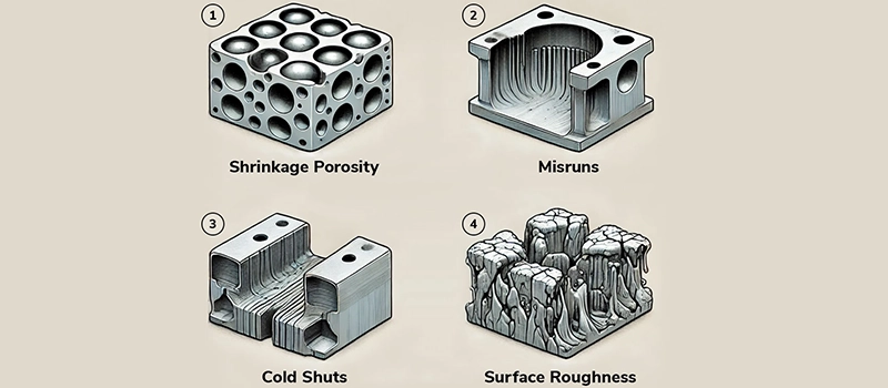
Shrinkage Indicators in Production
Surface Sinks and Visual Deformation
One of the most visible signs of shrinkage in die-casting is the formation of surface sinks. These appear as shallow depressions, often in thicker wall sections or broad planar surfaces. Surface sinks are a result of material volume loss during cooling, compounded by insufficient feeding or poor die temperature control.
Pattern and Location
Sinks often appear at rib intersections, boss bases, or near isolated heat-retaining features. These are typical zones where shrinkage in die-casting concentrates due to thermal gradients and delayed solidification.
Internal Voids and Porosity Formation
Shrinkage in die-casting frequently results in internal voids that are not visible on the surface. These voids form when the final zones of the casting solidify without continued pressure or molten metal feed. Internally, this manifests as porosity or discrete gas pockets, reducing both mechanical strength and sealing reliability.
Differentiating Shrinkage vs. Gas Porosity
While gas porosity tends to form near surfaces and appears spherical, shrinkage-related porosity is typically irregular and found deeper within the casting. Identifying the shrinkage mechanism helps determine if the defect is thermal in origin or due to gas entrapment during filling.
Dimensional Inaccuracy and Distortion
Another outcome of shrinkage in die-casting is dimensional deviation. Parts may appear undersized, warped, or misaligned relative to tooling dimensions. This is not always immediately visible but becomes clear during post-machining or final assembly.
Machining Reference Misalignment
Shrinkage can shift critical datums, bore centers, or sealing faces. When machining fixtures rely on distorted features, this introduces compounding dimensional errors downstream. Shrinkage must be accounted for in both part design and machining setup to prevent systemic misalignment.
Key Factors That Influence Shrinkage
Alloy Composition and Thermal Behavior
The metallurgical properties of the alloy directly affect how shrinkage in die-casting manifests. Alloys with a wide solidification range, such as aluminum-silicon systems, are more prone to shrinkage voids due to prolonged mushy zones. In contrast, zinc alloys with narrow freezing ranges tend to shrink uniformly, making them easier to manage under consistent process conditions.
Volume Change and Feeding Resistance
Each alloy contracts differently as it cools. Alloys with high volume change between liquid and solid phases require aggressive feeding and pressure maintenance. Without this, shrinkage in die-casting leads to internal collapse and dimensional instability. Feeding resistance increases with viscosity, solid fraction buildup, and oxide formation during solidification.
Mold Geometry and Wall Thickness Distribution
Non-uniform wall thickness is a major contributor to shrinkage in die-casting. Thick sections solidify more slowly, trapping liquid metal and generating stress as thinner areas lock in first. These thermal delays create isolated zones that pull away from surrounding material as volume is lost during cooling.
Hot Spots and Thermal Imbalance
Geometries with uneven mass distribution cause hot spots. These areas remain molten after the rest of the casting has solidified, but are no longer connected to the gate or runners. The result is trapped shrinkage that cannot be compensated. Proper thermal balance through uniform wall design is critical.
Die Temperature and Cooling Rate Management
Controlling die temperature is essential to managing shrinkage in die-casting. Uneven die heating causes thermal asymmetry, where one side of the part shrinks more than the other. This leads to warping, residual stress, or concentrated sink marks.
Cooling Channel Design
Cooling lines must be positioned to support directional solidification. If cooling is too aggressive near gates and insufficient near the last-to-fill zones, shrinkage concentrates in deep cavities or thick cores. Poor thermal layout increases cycle variation and defect rates.
Gating and Venting Design Efficiency
The gating system determines how molten metal enters the cavity, how pressure is maintained, and whether air and gases are properly evacuated. Poorly designed gates or blocked vents disrupt flow, causing shrinkage in die-casting through incomplete fill or early solidification.
Pressure Transmission and Isolation
Shrinkage-related defects increase when hydraulic pressure can’t be sustained in isolated zones. Gating systems that split flow paths without reinforcement create dead zones where feeding is impossible. Optimizing gate size, runner layout, and overflow position is key to reducing volumetric loss during solidification.
Methods to Reduce Shrinkage in Die-Casting
Alloy Selection and Control
Controlling shrinkage in die-casting begins with alloy selection. Alloys with narrow freezing ranges solidify more predictably, reducing the likelihood of internal voids. For example, aluminum-silicon alloys with eutectic compositions tend to shrink more uniformly, while non-eutectic blends with extended mushy zones require more precise feeding and thermal control.
Chemistry Consistency
Alloy variation from batch to batch affects shrinkage response. Impurities, oxides, and gas content influence how the metal solidifies and contracts. Maintaining tight chemical control is essential to achieve repeatable shrinkage behavior across production runs.
Optimized Mold Design
Die geometry and thermal flow must be engineered to direct solidification in a controlled sequence. Uniform wall thickness reduces thermal imbalance. Ribs, bosses, and transitions should be blended to avoid isolated mass accumulation, where shrinkage in die-casting typically concentrates.
Overflow Placement and Feed Strategy
Well-placed overflows help draw metal into final fill areas. Without these, the last-to-solidify zones become unsupported and prone to internal shrinkage. Strategic use of feed pads and pressure intensification zones can provide late-stage compensation where direct feeding is not possible.
Controlled Cooling System Layout
Cooling lines must be designed to manage thermal gradients and promote directional solidification. Uneven or poorly balanced cooling increases cycle time variation and defect probability. Water lines, baffles, and chill inserts must align with known hot spots and last-to-freeze regions.
Cycle Time Calibration
Process consistency depends on thermal stability. Excessive cycling variation—caused by poor heat extraction or unstable mold temperatures—amplifies the risk of shrinkage in die-casting. Cooling circuits must be designed for both localized and system-wide balance.
Process Parameter Tuning
Holding pressure, injection speed, and fill time directly affect feeding behavior during solidification. Higher intensification pressure during the final stage improves material feed into shrinking areas. However, excessive pressure without proper gating design may cause flash or die fatigue.
Shot Profile Optimization
A staged shot profile—high velocity for cavity fill, followed by controlled pressure intensification—allows the system to maintain metal feed during the critical solidification window. Pressure drop timing must be matched to alloy response to prevent shrinkage voids.
Inspection and Measurement of Shrinkage Defects
Visual Indicators and Surface Analysis
Surface defects caused by shrinkage in die-casting often appear as sink marks, depressions, or localized wrinkling. These features are typically found near thick wall sections, bosses, ribs, and areas distant from gating systems. Visual inspection remains the first layer of defect detection, but its reliability depends heavily on lighting, angle, and inspector training.
Limitations of Surface-Based Inspection
Surface shrinkage may not correlate with internal voids. A casting may appear sound externally but contain severe volumetric loss. Reliance on visual cues alone increases the risk of latent failure in downstream operations.
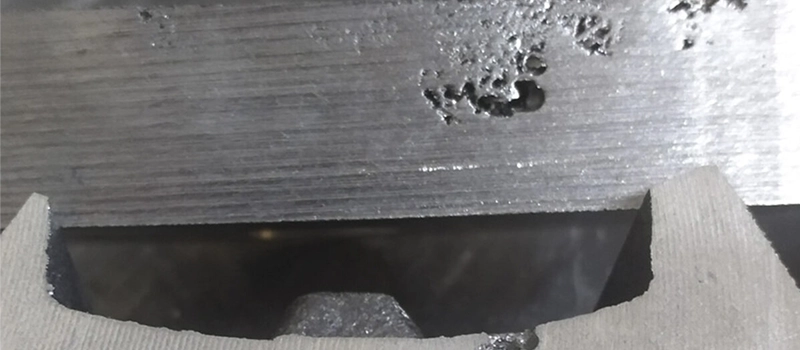
X-Ray and CT Scanning for Internal Voids
Shrinkage in die-casting is most accurately diagnosed using radiographic methods. X-ray inspection reveals internal porosity and collapsed cavities not visible on the surface. These voids tend to concentrate around thermal hotspots, where late-stage solidification occurred without adequate feeding.
Use of Industrial CT
Computed tomography (CT) scanning provides full 3D visualization of internal structure. It allows for the measurement of pore volume, distribution, and orientation. This is especially useful for validating die designs, calibrating simulations, or qualifying tooling changes. Though not always used in production, CT is critical for first article inspection and failure analysis.
Dimensional Inspection and CMM Verification
Shrinkage in die-casting also causes geometric shifts that may not present as obvious defects. Parts may be within visual spec but fail when inspected against GD&T features. Coordinate Measuring Machines (CMM) allow precise verification of flatness, concentricity, bore alignment, and profile tolerances.
Deviation Mapping and Trend Monitoring
Digital inspection data can be mapped against nominal models to detect consistent distortion patterns. Over time, this information helps identify zones where shrinkage is recurring and process adjustments are necessary. Data trends also highlight die wear or thermal fatigue that may be amplifying shrinkage behavior.
Design Guidelines for Minimizing Shrinkage
Uniform Wall Thickness and Fillet Radii
One of the most effective ways to reduce shrinkage in die-casting is to maintain uniform wall thickness throughout the part. Irregular sections—such as abrupt transitions from thick to thin—create thermal imbalance, leading to uneven solidification and shrinkage pockets. Design should avoid sudden changes in cross-section and use gradual tapers or fillets to ease metal flow and cooling.
Preventing Isolated Mass Accumulation
Isolated thick features, like unsupported bosses or localized ribs, retain heat longer than surrounding areas. These zones frequently become sites of shrinkage in die-casting, especially when located far from feeding paths. Uniform mass distribution supports directional solidification and consistent shrinkage behavior.
Predictive Simulation of Solidification
Modern casting simulation software allows engineers to model metal flow, temperature gradients, and solidification profiles before tooling is cut. Shrinkage in die-casting can be predicted with high accuracy by running virtual trials of gating layouts, cooling line positions, and alloy behavior under different fill conditions.
Using Simulation for Tooling Feedback
Simulation data helps identify hot spots, incomplete feeding, and solidification traps. This enables preemptive changes to die geometry or cooling strategy, reducing the likelihood of shrinkage-related defects before production begins. Simulations should also reflect realistic process parameters—cycle time, die temperature, fill velocity—to ensure results correlate with actual casting behavior.
Placement of Overflows and Feeders
Strategically placed overflows and feeders compensate for volume loss during solidification. These features direct additional metal to the final zones to solidify, offsetting local shrinkage in die-casting. Without such elements, molten metal becomes trapped behind prematurely solidified regions and cannot feed internal voids.
Reinforcing Pressure and Flow Paths
The positioning of gates, runners, and overflows affects the pressure profile during injection. Feeders must be located near shrinkage-prone zones and designed to maintain pressure through the critical phase of solidification. Overflows also serve as thermal dumps, drawing heat away from solidification zones and promoting structural soundness.
Where Shrinkage Reduction Strategies Fail
Misaligned Process Parameters
Even with well-designed parts and tooling, shrinkage in die-casting will persist if process parameters are unstable or mismatched to the material. Injection speed, holding pressure, and cycle time must be tightly controlled. When shot profiles vary between cycles, or pressure drop occurs too early during solidification, feeding is interrupted. This inconsistency opens the path for localized voids and sinks.
Overshooting or Undershooting Pressure Windows
Holding pressure that is too low fails to compensate for volumetric contraction. Excessive pressure, on the other hand, may cause flashing or die distortion. Both conditions weaken the system’s ability to resist shrinkage in die-casting, especially in deep or thermally isolated sections.
Incorrect Alloy–Die Configuration
Shrinkage control depends on more than alloy properties—it requires alignment between material behavior and die thermal performance. Alloys with long solidification ranges demand slower cooling, broader gates, and longer hold times. When a die designed for a short-freezing alloy is used with one prone to mushy solidification, shrinkage in die-casting becomes inevitable, regardless of tooling quality.
Thermal Lag and Alloy Incompatibility
Improper pairing leads to hot spots, poor feeding, and residual stress. Die sections may remain molten longer than the system can feed them, producing internal cavities that simulation alone won’t always predict. Recognizing alloy-specific thermal needs is critical.
Underestimated Cooling Imbalance
In many cases, the root cause of persistent shrinkage in die-casting lies in uneven die cooling. Even small variations in water line effectiveness or channel depth create thermal zones that solidify out of sequence. This mismatch traps molten metal and prevents proper feeding, even when gating appears correct.
Gradual Cycle Drift
Over time, slight changes in cooling efficiency, thermal wear, or buildup of scale inside channels lead to temperature drift. What was once a balanced cycle becomes skewed, amplifying shrinkage risk. The process fails not from sudden change, but from slow degradation of heat flow and thermal consistency.
Shrinkage Inspection and Data Feedback
Inline Measurement and Real-Time Tracking
To consistently manage shrinkage in die-casting, inspection must be integrated into the production flow. Traditional post-process inspection is reactive; inline measurement tools offer immediate detection. Sensors that track die temperature, cycle time, injection pressure, and cooling rates can indicate thermal drift or parameter deviation long before shrinkage defects appear in finished parts.
Real-Time Alerts and Threshold Management
Modern die-casting machines can be programmed with alarm thresholds for critical variables. Deviations in intensification pressure, metal temperature, or shot velocity often correlate with shrinkage-prone conditions. These signals form the first layer of defense against systemic process variation.
X-Ray Feedback Loops
Radiographic inspection doesn’t just detect shrinkage—it also informs process corrections. Comparing X-ray images across production batches helps isolate repeatable shrinkage in die-casting zones. Mapping these zones against simulation and mold layout data creates a closed feedback loop that informs gating revisions or thermal upgrades.
Linking Image Data to Process History
Tagging X-ray results with cycle-specific parameters enables root cause analysis. For example, if shrinkage increases at higher die temperatures or longer fill times, those conditions can be tuned out of the process envelope. Defect data gains more value when it is matched with real-time production variables.
Statistical Process Control (SPC) for Shrinkage Trends
Shrinkage in die-casting tends to follow trends, not isolated events. Dimensional measurements across hundreds of parts reveal gradual drift or out-of-control conditions. SPC tools help track this movement, signaling when maintenance, mold cleaning, or parameter re-calibration is needed.
Establishing Predictive Thresholds
Over time, data sets from CMM, CT, and inline metrics form a predictive model. This allows process teams to forecast shrinkage behavior under different setups. Predictive control doesn’t eliminate shrinkage—it keeps it below functional or cosmetic thresholds.
Conclusion
Shrinkage in die-casting is a controlled variable, not an unpredictable defect. When thermal balance, material behavior, and process control are aligned, shrinkage can be minimized to within functional limits. Reliability depends not on eliminating shrinkage, but on managing it within the constraints of design and production reality.