Depth of cut in machining is often treated as a routine setup step—but when incorrectly applied, it becomes one of the most frequent sources of tool wear, chatter, and dimensional error. Across turning, milling, and drilling, it’s a parameter that directly affects how efficiently and precisely material is removed.
The problem is that even minor miscalculations in cutting depth can cause a ripple effect—leading to unstable cutting forces, excessive heat, and shortened tool life. For operators running tight-tolerance jobs or high-speed roughing cycles, this issue becomes more than a productivity drain—it becomes a process risk.
Understanding how to define, limit, and optimize depth of cut in machining isn’t just a matter of fine-tuning—it’s a foundational control point for anyone working in metal cutting. In this article, we’ll examine how depth of cut interacts with material properties, tooling geometry, and machine stability—so you can avoid avoidable wear and achieve consistent cutting performance.
Understanding Depth of Cut
What Is Depth of Cut in Machining
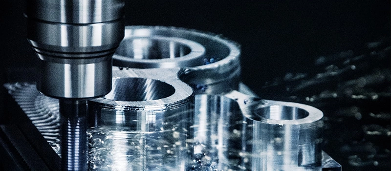
Depth of cut in machining refers to the thickness of the material layer removed by the cutting tool in a single pass. It is one of the three core cutting parameters, alongside cutting speed and feed rate. In turning operations, it is measured from the uncut surface to the machined surface, perpendicular to the feed direction. In milling, it is typically categorized into axial (along the spindle) and radial (perpendicular to the spindle) depths.
This measurement is expressed in millimeters or inches and directly correlates with the volume of material removed per pass. While the concept appears simple, small changes in depth significantly alter machining behavior. A deeper cut increases the load on the tool and machine, raising the risk of deflection, vibration, and wear.
The optimal depth of cut in machining depends on several interacting variables: material hardness, tool geometry, machine rigidity, and the purpose of the operation (roughing vs. finishing). Selecting the right depth is not about maximizing removal rate alone—it must also support tool stability, chip evacuation, and thermal control.

Types of Depth of Cut
In practice, there are different types of depth definitions depending on the machining process:
- Axial depth of cut: This is the depth parallel to the tool axis. In milling, it defines how deep the cutter engages vertically into the workpiece.
- Radial depth of cut: This measures engagement perpendicular to the spindle. It determines how much of the tool’s width is involved in cutting.
- Incremental depth of cut: Common in finishing passes or multi-step roughing, where each layer removes a specific thickness.
- Total depth of cut: The sum of all incremental passes required to reach the final profile.
Different machining strategies balance these depths based on machine limits and tool behavior. For example, high-speed milling often uses shallow radial depths with high feed rates to minimize heat and vibration. In contrast, heavy roughing operations may favor deeper axial cuts to reduce cycle time, assuming machine rigidity allows it.
Key Factors Affecting Depth of Cut
Material Properties
The material being machined plays a central role in determining the feasible depth of cut in machining. Softer materials like aluminum or brass can generally tolerate deeper cuts without causing excessive tool wear or machine load. In contrast, harder alloys such as titanium or hardened steels require shallower cuts to prevent tool edge chipping, thermal damage, or part deflection.
Work hardening behavior is also a critical consideration. Some materials, such as austenitic stainless steels, harden as they are cut. A depth that is too shallow may cause the tool to repeatedly cut through the hardened layer, leading to accelerated wear. A deeper initial pass may help avoid this, but only if the machine’s rigidity and tool condition can support it.
Additionally, materials with poor thermal conductivity—such as certain nickel alloys—generate more heat at the tool–workpiece interface. This heat can degrade coating performance and lead to premature tool failure. Therefore, allowable depth must be adjusted downward to maintain thermal balance and prevent heat-induced deformation or surface burns.
Tool Geometry and Strength
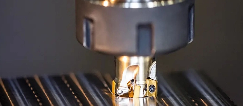
Tool design places direct constraints on depth of cut in machining. Tool nose radius, rake angle, insert type, and overall tool stiffness all influence how much material the tool can remove per pass without causing deflection or chatter.
For turning inserts, a larger nose radius distributes cutting forces more evenly and improves surface finish but also increases radial load. This may limit the depth of cut on less rigid setups. Similarly, tools with positive rake angles reduce cutting forces and support slightly deeper cuts, though they may be less durable in abrasive materials.
In milling, flute count and helix angle play major roles. Tools with fewer flutes offer better chip clearance and are suitable for deeper axial engagement. Higher helix angles help reduce vibration but may limit radial cutting engagement.
Tool holding also matters. Long overhangs or weak clamping reduce system stiffness and amplify vibration. Under these conditions, even moderate depths of cut can produce chatter marks, tolerance shifts, and unstable cutting behavior.

Machine Stability and Power
The physical capabilities of the machine tool set hard limits on depth of cut in machining. Lower-power machines with limited spindle torque cannot maintain cutting performance under heavy loads. Attempting deep cuts on such machines causes spindle slowdowns, tool deflection, and inconsistent finishes.
Machine rigidity is equally important. Any structural deflection in the bed, column, or spindle causes positional error during engagement. CNC machines with box ways and heavy frames are better suited to handle deeper cuts without stability loss.
For CNC programmers and manufacturing engineers, machine limits should always be included in tooling calculations. Many manufacturers provide spindle power curves and recommended load conditions, which should be cross-referenced with expected cutting forces generated at the desired depth.
Impacts of Incorrect Depth of Cut
Tool Wear and Premature Failure
Choosing the wrong depth of cut in machining—especially an overly aggressive one—can significantly reduce tool life. Excessive depth increases cutting forces beyond what the insert or cutter is designed to handle. This leads to micro-chipping at the tool edge, accelerated coating degradation, and in many cases, catastrophic failure under load.
Even when a tool doesn’t fracture, constant overload from improper depth of cut in machining results in thermal stress. Heat accumulation at the tool–workpiece interface breaks down the cutting edge and causes flank wear or crater wear. In dry machining or low-lubricity environments, this degradation becomes even more pronounced.
On the other hand, an overly shallow depth of cut in machining can also increase wear if it causes the tool to rub instead of cut. This is especially true when the tool re-engages in work-hardened material, causing edge rounding and loss of cutting effectiveness. In both cases, choosing the correct depth is a key factor in preserving tool performance and reducing changeover downtime.
Surface Finish and Dimensional Accuracy
Surface quality is another area directly affected by the selected depth of cut in machining. Deep cuts can cause tool deflection, especially in slender tools or unsupported workpieces. This results in tapering, size deviation, and inconsistent geometry that may fall outside of tolerance.
In finishing operations, even a slight increase in depth of cut in machining may introduce visible tool marks or surface waviness due to increased radial forces. Moreover, chatter—caused by improper engagement between the tool and the part—can leave unacceptable surface patterns that require additional processing or rejection.
Precision operations such as die finishing, bearing seat turning, or close-tolerance milling rely on very controlled depth of cut in machining to maintain uniformity. Deviation in depth from vibration, spindle flex, or tool wear can compromise fit and functional performance, leading to rework or scrap.
Thermal and Mechanical Load Risks
Incorrect depth of cut in machining doesn’t just affect tools and surfaces—it also puts mechanical stress on the machine tool and spindle. Cutting forces increase exponentially with depth, and if not properly controlled, this overload can damage drive systems or reduce machine accuracy over time.
Heat generation rises with increased material engagement. This heat is not always dissipated effectively, especially in dry machining or difficult-to-machine materials. Elevated temperatures cause thermal expansion in both tool and workpiece, introducing dimensional shifts and reducing consistency in repeat runs.
How to Select Optimal Depth of Cut
Based on Material and Tool Pairing
Selecting the right depth of cut in machining begins with understanding the material–tool interaction. Harder metals like tool steels, Inconel, or titanium require shallower depths to avoid rapid tool degradation. In contrast, softer materials like aluminum, brass, and mild steels allow for more aggressive cutting depths without compromising surface quality or tool life.
Tooling characteristics must be matched accordingly. For coated carbide inserts or solid carbide end mills, the depth of cut in machining should stay within manufacturer-recommended values based on coating thickness and edge preparation. For high-speed steel (HSS) tools, which are more heat-sensitive, a conservative depth is advised, especially during continuous cuts.
The goal is to find a balanced value of depth of cut in machining that doesn’t exceed the tool’s capacity to evacuate chips, maintain edge sharpness, and resist flexing under stress. Using cutting handbooks or tool supplier guidelines helps establish safe baseline depths tailored to the specific material and tooling configuration.
Based on Operation Goals
Machining strategy plays a critical role in setting the correct depth of cut in machining. For roughing operations, where productivity and material removal rate (MRR) are prioritized, deeper cuts are typically used in combination with lower spindle speeds and higher feed rates. The aim is to remove as much material as possible in fewer passes, while staying within tool load limits.
Finishing operations, by contrast, use very small depths of cut in machining—often less than 0.25 mm (0.01 in)—to ensure a clean, controlled surface without introducing stress or deflection. In these cases, the depth is chosen not to maximize removal but to stabilize the tool and eliminate chatter or vibration.
High-precision jobs, especially those involving tight tolerances or fine surface finish requirements, rely on incremental passes with consistent depth of cut in machining to minimize risk. Finishing tools are usually shorter and stiffer to allow shallower cuts without tool deflection.
Based on Machine Capability
Machine power and rigidity must also inform your decision. A depth that is optimal on a large-frame CNC lathe may exceed the capability of a compact vertical mill. Torque, spindle stiffness, guideway rigidity, and workholding must all support the applied depth of cut in machining without introducing mechanical instability.
CAM simulation tools and process monitoring systems allow machinists to model expected loads at various cutting depths. These simulations help predict deflection and flag settings that could overload spindles or exceed power curves. Whenever machine capacity is in question, starting with conservative depths and gradually scaling up ensures safety and tool protection.
Depth of Cut and Productivity
Material Removal Rate (MRR) Efficiency
The depth of cut in machining is one of the three variables that directly influences material removal rate, along with feed rate and cutting speed. For roughing operations, increasing depth is the most efficient way to raise MRR without significantly extending tool path length. A deeper cut means fewer passes, which directly translates to shorter cycle times.
However, increasing depth of cut in machining comes with consequences. Higher cutting forces place stress on the spindle, the tool holder, and the machine structure. If the system isn’t rigid enough to support these loads, the resulting deflection can cause part inaccuracy or poor surface integrity. This creates a trade-off: higher productivity versus potential loss in dimensional control.
For machining centers equipped with high-torque spindles and rigid frames, depth of cut in machining can be pushed closer to the tool’s upper threshold. These machines are designed to handle deeper cuts at stable feed rates without sacrificing surface finish or tool longevity. However, the operator must still monitor for vibration, chip evacuation issues, and thermal buildup.
Balancing Speed, Tool Wear, and Finish
Maximizing productivity isn’t just about cutting deeper—it’s about balancing depth of cut in machining with tool life and part quality. Aggressive depth settings increase throughput but also accelerate insert wear, especially at the tool nose where cutting forces are concentrated.
If finishing operations are required after roughing, the strategy must ensure that enough stock is left for a final, shallow depth of cut that corrects for any deformation caused earlier. This ensures that the finish pass does not simply follow previous tool deflection or chatter marks.
In automated production lines, consistent depth of cut in machining ensures predictability in tool wear patterns and part outcomes. Deviations in depth—whether from tool deflection, workpiece inconsistency, or program error—introduce variability that disrupts downstream processes. High-volume environments benefit from controlled, repeatable depth values that optimize both speed and quality.
Effective productivity planning requires understanding how depth of cut in machining interacts with machine capacity, tool selection, and process goals. It’s not just a number—it’s a control point for throughput, consistency, and efficiency.
Practical Tips for Depth of Cut Control
Start with Manufacturer Guidelines
When determining the right depth of cut in machining, the safest starting point is always the tool manufacturer’s recommendations. Most insert and end mill datasheets provide a range for both axial and radial depths, adjusted by material group. These values are based on controlled tests and reflect real cutting performance, tool strength, and heat tolerance.
Exceeding the recommended depth of cut in machining without understanding tool limitations can lead to unpredictable behavior, including chatter, nose breakage, or work hardening. Manufacturers also provide guidelines for adjusting depth when using coolant, different coatings, or varying cutting speeds. Following these ensures stable operation within the tool’s performance envelope.

Adjust Incrementally and Monitor
Depth of cut in machining should not be adjusted in large increments without validating performance. A small change—especially on hard-to-machine materials—can drastically increase cutting forces and impact part quality. When scaling up, always use trial passes at slightly increasing depths and inspect for vibration, tool wear, and finish degradation.
Many modern CNC systems include adaptive control or load monitoring that tracks spindle load in real time. These tools help detect if the depth of cut in machining is pushing the system beyond its stable threshold. If load spikes or tool vibration increase, depth should be reduced before continuing.
For manual machines, operators should visually inspect chips. Discoloration, fine powdery chips, or irregular shapes may indicate that the tool is not engaging the material effectively. In these cases, depth adjustments should be paired with feed and speed corrections to balance the load.
Use CAM Software Simulations
Before machining begins, simulation tools built into CAM software can calculate expected loads based on toolpath and depth of cut. These simulations model chip thickness, engagement angle, and cutting force across the entire pass. They are especially useful for predicting risks on complex geometries or high-speed toolpaths.
By entering realistic values for tool diameter, stick-out, and spindle power, the software can help validate whether the selected depth of cut in machining is appropriate. Any overload warnings or collision risks should prompt a reevaluation of cutting parameters.
Simulation data allows engineers to avoid guesswork and reduce trial-and-error on the shop floor. It’s an essential tool when pushing depth limits on expensive parts or large production runs.
Conclusion
Depth of cut in machining is not a fixed number—it’s a strategic control that affects tool wear, surface finish, machine load, and overall productivity. When properly selected and monitored, it improves efficiency and dimensional stability across processes. Misjudging it, however, leads to unnecessary wear, part rejection, and cycle delays. Understanding its limits and applications ensures consistent, reliable machining outcomes.