Why do sheet metal assemblies fail to align even when dimensions appear correct?
Why do corner cracks appear after bending despite proper material selection?
Why does tolerance drift occur between flat patterns and formed parts?
In many cases, the underlying issue is overlooked sheet metal notching behavior.
According to guidance from international sheet metal forming and fabrication standards bodies,corner relief and notch geometry directly influence stress distribution during forming.
Improper sheet metal notching introduces localized stress concentration, unstable material flow, and unpredictable deformation.
These issues are rarely visible at the flat stage but become critical during bending and final assembly.
A clear understanding of sheet metal notching is essential to maintain assembly accuracy, control tolerance buildup, and prevent avoidable production failures.
What Sheet Metal Notching Means in Practical Manufacturing
Definition of Sheet Metal Notching
Sheet metal notching is the intentional removal of material from a flat sheet metal blank before forming. Its purpose is to control deformation during bending and provide clearance at intersecting bends. In manufacturing, sheet metal notching is a functional design element defined before production, not an adjustment made afterward.
During bending, material near corners experiences uneven strain. Sheet metal notching modifies these high-stress areas, allowing material to flow along the bend line without tearing or distortion. When notching is correctly sized, formed geometry remains predictable through assembly.
What Sheet Metal Notching Is Not
Sheet metal notching is not post-forming trimming. Once bending deformation occurs, trimming cannot correct internal stress distribution. It is also not a corrective solution for poor bend radius selection or improper forming sequence.
Notching should not be treated as a cosmetic feature or simplified for appearance. Reducing or reshaping notches without considering material behavior increases the risk of cracking and dimensional instability.
Why Sheet Metal Notching Exists in Sheet Metal Design
Sheet metal notching exists to reduce stress concentration at bend intersections. Without proper relief, strain accumulates at internal corners, leading to cracking or uncontrolled deformation during forming.
Notching also prevents material interference when multiple flanges are bent. Insufficient clearance alters bend angles and shifts final dimensions. Proper sheet metal notching stabilizes forming behavior and improves assembly accuracy by limiting tolerance drift.
How Sheet Metal Notching Influences Assembly Accuracy
Stress Concentration Introduced by Sheet Metal Notching
Sheet metal notching directly changes where stress accumulates during bending. At internal corners and intersecting bend lines, stress naturally concentrates. If the notch geometry is too sharp or too shallow, stress localizes at the notch root instead of being redistributed along the bend. This condition increases the risk of cracking and permanent deformation that cannot be corrected during assembly.
Proper sheet metal notching reduces peak stress by smoothing the transition between bend zones. Radius size and notch shape determine whether stress is dispersed or trapped. When stress remains localized, small variations in material properties or forming force result in inconsistent part geometry.
Material Flow Disruption During Bending
During bending, sheet metal flows plastically around the neutral axis. Sheet metal notching interrupts this flow. If the notch does not align with the bend direction or is improperly proportioned, material flow becomes asymmetric. This asymmetry causes angular deviation and local twist.
In multi-bend parts, disrupted material flow compounds across forming steps. A notch that appears acceptable after the first bend may cause misalignment after subsequent bends. This is why sheet metal notching must be evaluated with the full forming sequence in mind, not as a single operation.
Relationship Between Sheet Metal Notching and Tolerance Stack-Up
Sheet metal notching has a direct effect on tolerance accumulation. Variations at notched corners translate into angular errors after bending. These angular errors increase positional deviation at assembly interfaces, such as holes, slots, and mating edges.
When multiple notched features exist on one part, small deviations add together. Even if each notch falls within its individual tolerance, the assembled component may exceed allowable limits. Controlling sheet metal notching geometry is therefore a primary method for limiting tolerance stack-up and maintaining assembly accuracy.
Common Sheet Metal Notching Methods Used in Production
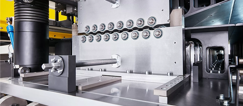
Punch Notching in Progressive and Standalone Operations
Punch notching is widely used for high-volume production where repeatability is required. The process relies on dedicated tooling to remove material in a single stroke. Dimensional consistency is generally good when tooling is maintained, but edge quality degrades as tools wear.
Tool wear has a direct impact on corner sharpness and burr formation. As wear increases, stress concentration at the notch root also increases, even if nominal dimensions remain unchanged. This often explains why forming issues appear gradually rather than immediately. Regular inspection of punch condition is therefore critical for maintaining stable forming behavior.
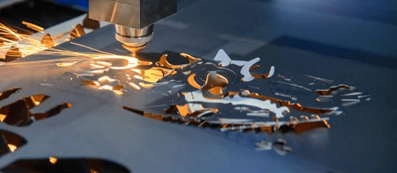
Laser Notching
Laser cutting is commonly used for low- to medium-volume production and complex geometries. It provides high positional accuracy and design flexibility, especially for internal corners and variable notch shapes. However, laser processing introduces localized thermal effects.
Heat-affected zones alter material hardness near the cut edge. In thin or work-hardening materials, this can reduce ductility at the notch root. If bend lines are close to laser-cut notches, cracking risk increases. Laser notching requires careful coordination between cut geometry and forming sequence.
Turret Press Notching
Turret presses combine flexibility with moderate production speed. Notches are often created through nibbling rather than a single hit. This produces stepped edges that may appear acceptable in flat inspection but behave differently during bending.
The segmented edge profile increases friction and disrupts material flow. Without secondary finishing, nibble marks can act as unintended stress risers. This method requires conservative geometry and sufficient clearance to avoid forming instability.
Secondary Machining for Notching
Machining is occasionally used when tight control over geometry is required or when correcting pre-cut blanks. It provides clean edges and controlled radii but increases cost and cycle time.
Machined notches are typically reserved for critical interfaces or thick materials where forming forces are high. They are not a substitute for proper design but may be justified when assembly accuracy is highly sensitive to corner geometry.
Sheet Metal Notching Geometry Rules That Affect Fit and Alignment
V-Notch, U-Notch, and Rectangular Notch Behavior
Notch shape determines how strain is released during bending. V-shaped reliefs concentrate deformation toward a point and are sensitive to radius control. Small variations in cut quality or material condition can shift where cracking initiates. This shape is typically used only when space is limited and bend angles are moderate.
U-shaped reliefs distribute strain more evenly. The rounded base reduces peak stress and improves consistency across forming batches. For parts with repeated bends or tighter tolerances, this geometry is generally more stable.
Rectangular reliefs provide maximum clearance but remove more material than necessary. While they reduce interference risk, they also weaken corner stiffness. Excessive clearance often leads to angular drift and loss of positional accuracy after forming.
Minimum Notch Radius and Crack Prevention
Internal radius at the notch root is a primary control point for crack resistance. Sharp corners act as stress risers regardless of material grade. Even ductile materials will crack if the radius is too small relative to thickness and bend severity.
Increasing the internal radius lowers peak strain but must be balanced against available clearance. A radius that is too large can interfere with mating parts or reduce contact area. Practical radius selection depends on material ductility and bend proximity.
Notch Depth Relative to Material Thickness
Notch depth controls whether flanges can complete their bend without interference. Insufficient depth causes material collision before the target angle is reached. This shifts the bend line and alters final dimensions.
Excessive depth removes structural continuity at corners. This increases springback variation and makes parts sensitive to handling and secondary operations. Depth should be sufficient for clearance but limited to what forming actually requires.
Practical Geometry Limits for Carbon Steel, Stainless Steel, Aluminum
Lower-carbon steels tolerate smaller radii and shallower reliefs due to stable plastic flow. Stainless steels require more conservative geometry because work hardening amplifies stress at cut edges. Aluminum alloys demand the most generous relief, as low yield strength and tear sensitivity magnify notch effects during bending.
If you want me to continue, the next section will cover production failures caused by improper geometry, using the same reduced keyword density and concise structure.
Production Failures Caused by Improper Sheet Metal Notching

Corner Cracking After Bending
Corner cracking is one of the earliest indicators of poor notch design. Cracks usually initiate at the notch root, not along the bend line itself. This is because strain concentrates where cut geometry interrupts material continuity. Even when material grade and thickness are correct, inadequate relief geometry causes localized overstressing during forming.
These cracks may be microscopic at first and pass visual inspection. They often propagate later during handling, welding, or service loading. Once cracking appears, corrective action is limited, since the failure mechanism is embedded in the formed geometry.
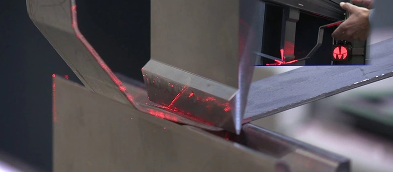
Angular Deviation and Part Twist
Improper relief geometry alters how material releases stress after bending. When deformation is uneven, springback becomes inconsistent across the part. This results in angular deviation that cannot be corrected by adjusting press brake settings alone.
In parts with multiple bends, uneven stress release causes twist. Twist is particularly problematic because it may not be detectable with simple linear measurements. Assemblies then rely on force fitting, which introduces additional stress and accelerates fatigue.
Fastener and Hole Misalignment
Misalignment of holes and slots is a common downstream effect. Even small angular errors at corners shift hole positions significantly over distance. When fasteners no longer align, assembly requires reaming, slotting, or forced installation.
These corrective actions reduce joint integrity and increase variability. In welded assemblies, misalignment also affects weld penetration and bead consistency, leading to secondary quality issues.
Scrap, Rework, and Delivery Delays
Failures caused by notch geometry often appear late in the production process. Parts may pass cutting and forming inspection but fail during assembly. At this stage, rework is time-consuming and scrap rates increase sharply.
Delivery schedules are affected because corrective actions usually require design changes rather than process adjustments. This disrupts production planning and increases overall cost, even when the individual defect appears minor.
Sheet Metal Notching Tolerances and Inspection Control
Typical Tolerance Ranges in Sheet Metal Notching
Tolerance control at notched features is often underestimated because inspection focuses on overall flat dimensions. In practice, allowable variation depends on material thickness, notch geometry, and proximity to bend lines. Industry guidelines and fabrication standards indicate that tighter control is required when notches intersect with forming zones.
When tolerance limits are defined too loosely, small variations at the notch root translate into angular deviation after bending. These deviations are rarely symmetrical, which makes correction through press brake adjustment ineffective. Proper tolerance definition must therefore consider formed geometry, not just flat pattern dimensions.
Visual Inspection Versus Dimensional Measurement
Visual inspection can identify obvious defects such as burrs, tearing, or incomplete cuts. However, it cannot detect subtle geometric inconsistencies that influence forming behavior. Notch radius, edge condition, and symmetry often appear acceptable while still introducing instability during bending.
Dimensional measurement of critical features is more reliable, especially when combined with forming trials. Measuring internal radii and notch depth relative to bend lines provides better correlation with assembly performance. Relying solely on visual checks increases the risk of late-stage failures.
When Notching Tolerances Affect Final Assembly
Not all notched features are equally critical. Features located away from bends or assembly interfaces may tolerate wider variation without functional impact. In contrast, notches near fasteners, welds, or alignment surfaces directly affect fit.
Identifying which notches are functionally critical allows inspection effort to be focused where it matters. This approach reduces unnecessary inspection while improving control over assembly accuracy and repeatability.
Material-Specific Behavior in Sheet Metal Notching
Behavior in Low Carbon Steel
Low carbon steel exhibits relatively stable plastic flow during bending. Relief geometry can be modest as long as internal radii are controlled and edge quality is consistent. Variations in notch size usually result in gradual dimensional drift rather than sudden failure.
However, repeated forming operations amplify small inconsistencies. When multiple bends converge, even ductile steel will show angular variation if relief geometry is not uniform. Consistency matters more than aggressive clearance.
Behavior in Stainless Steel
Stainless steel is more sensitive to notch geometry due to work hardening. As deformation progresses, localized hardness increases near cut edges. If relief radii are too small, strain accumulates rapidly at the notch root.
This behavior leads to early cracking or unpredictable springback. Stainless components therefore require more conservative geometry and closer control of edge condition. Heat input during cutting also becomes a factor, especially when bends are close to notches.
Behavior in Aluminum
Aluminum alloys deform easily but tear readily at stress concentrations. Relief depth and radius must be sufficient to prevent tearing during bending, particularly in thinner gauges. Sharp internal corners are a frequent cause of failure.
Because aluminum has low yield strength, excessive clearance can also reduce stiffness. Parts may meet dimensional requirements initially but distort during handling or assembly. Balance between clearance and structural continuity is critical.
How Ductility Influences Geometry Decisions
Material ductility defines how much strain can be redistributed away from corners. Less ductile materials require larger radii and smoother transitions. More ductile materials tolerate tighter geometry but still require consistency.
Selecting relief geometry without considering material behavior leads to either premature failure or unnecessary loss of stiffness. Material properties must therefore guide design decisions rather than nominal thickness alone.
When Sheet Metal Notching Should Be Modified or Avoided
Alternative Design Approaches
Notching is not always the most stable solution for corner relief. In some designs, adjusting flange length or changing the bend sequence achieves the same clearance with less disruption to material flow. Extending or shortening a flange can move the interference zone away from high-stress areas without removing additional material.
Another alternative is the use of formed reliefs created through controlled bending rather than cutting. These approaches preserve material continuity and reduce stress concentration, particularly in parts where structural stiffness at corners is important.
Adjusting Forming Strategy Instead of Geometry
In certain cases, forming instability originates from the bend order rather than the relief shape. Changing the forming sequence can allow bends to complete without collision, reducing the need for aggressive clearance. This approach is especially effective in multi-bend parts where early bends restrict later operations.
Tooling selection also plays a role. Different punch and die combinations can accommodate tighter geometry without increasing stress. Before modifying cut geometry, forming parameters should be reviewed to determine whether the issue is process-related rather than design-related.
Situations Where Notching Creates More Risk Than Value
Notching should be avoided when it removes load-bearing material from critical corners. In parts subjected to vibration, fatigue, or dynamic loading, excessive relief weakens structural continuity and accelerates failure.
It should also be avoided when tolerances are extremely tight and clearance variation directly affects alignment. In these cases, the variability introduced by cutting often outweighs the forming benefit. When notching adds uncertainty rather than control, alternative design or forming solutions are usually more effective.
Conclusion
Sheet metal notching directly influences how a part deforms during forming and how accurately it assembles afterward. When notch geometry is defined with material behavior and forming sequence in mind, assembly accuracy becomes predictable rather than corrective. Poorly considered notching, by contrast, introduces hidden variability that surfaces only at the final assembly stage.