Have you ever faced issues where casted parts just don’t fit during assembly? Or maybe you’ve seen rejections from clients because dimensions were slightly off, even though you thought your design was accurate? These challenges often boil down to one critical concept: die casting tolerances.
Die casting tolerances are the foundation of precision and quality in metal manufacturing. By defining the allowable dimensional variation in a part, tolerances determine whether components can be assembled seamlessly, operate reliably, and meet strict industry standards.
Why does this matter to you? Because mastering tolerances means fewer defects, less waste, and stronger trust with your customers. In today’s competitive manufacturing environment, it’s not enough to just produce casted parts—you must produce them consistently within tolerance.
Types of Tolerances in Die Casting
Understanding the different types of die casting tolerances is essential for ensuring precision and quality. Each tolerance type serves a unique role in defining how accurately a part must be produced and how well it will perform in real-world applications.
Dimensional Tolerances
Dimensional tolerances define the acceptable variation in basic measurements such as:
- Length, width, and height of the part
- Wall thickness
- Hole diameters and positions
These are the most common tolerances in die casting and often follow standards such as ISO 2768.
Why They Matter
If dimensional tolerances are too loose, parts may not fit during assembly. If they are too tight, manufacturing costs rise due to increased machining and inspection requirements.
Geometric Tolerances
Geometric tolerances (GD&T) go beyond simple measurements to ensure the shape and orientation of features meet strict requirements.
They include controls for:
- Flatness
- Parallelism
- Concentricity
- Cylindricity
Why They Matter
These tolerances are critical in applications where moving parts interact, such as automotive transmissions or aerospace components. Even a slight geometric error can result in vibration, noise, or mechanical failure.
Linear and Angular Tolerances
These tolerances govern how straight or angled a part must be:
- Straightness and parallelism (linear)
- Angular alignment and deviation (angular)
Why They Matter
A small angular deviation can make an entire assembly impossible to complete. Proper control of these tolerances ensures reliable fit and function.
Surface Tolerances
Surface tolerances control the finish and texture of die cast parts. They often specify roughness levels measured in microns.
Why They Matter
- In electronics, smooth surfaces are essential for thermal contact.
- In automotive sealing applications, surface quality prevents leaks.
- In aerospace, controlled surface finish reduces friction and wear.
Application-Specific Tolerance Levels
The tolerance level required depends heavily on the end use of the part:
- Automotive fuel systems → very tight tolerances for safety and efficiency
- Construction equipment → moderate tolerances where ruggedness matters more than perfect fit
- Consumer products → balance between cost and acceptable accuracy
As a rule, smaller parts can achieve tighter tolerances, while larger castings are more difficult to control due to metal shrinkage and warping.
Industry Standards for Die Casting Tolerances (GD&T, ISO, DIN, JIS)
Die casting tolerances are not decided randomly. They are defined and controlled by international standards that ensure consistency, compatibility, and quality across industries. Knowing these standards is crucial for both manufacturers and buyers when discussing tolerance requirements.
Geometric Dimensioning and Tolerancing (GD&T)
GD&T is a global language of engineering drawings, used to describe tolerances for shape, form, orientation, and position.
Key GD&T Features in Die Casting
- Flatness → ensures a surface lies within two parallel planes
- Concentricity → ensures alignment of axes in cylindrical parts
- Perpendicularity → controls angular alignment of surfaces
- True position → defines exact location of holes or features
ISO Standards for Die Casting Tolerances
The International Organization for Standardization (ISO) provides globally recognized guidelines for tolerances.
Relevant ISO Standards
- ISO 2768 → general dimensional tolerances for linear/angular dimensions
- ISO 8062 → tolerance standards for castings, including die casting
- ISO 1101 → technical drawings using GD&T
DIN Standards (Germany)
The DIN (Deutsches Institut für Normung) standards are widely used in Europe, especially in Germany, one of the strongest markets for precision engineering.
Key DIN Reference
- DIN 1688 → covers dimensional tolerances for castings
JIS Standards (Japan)
The Japanese Industrial Standards (JIS) define tolerance practices commonly used in Asia.
Key JIS References
- JIS B 0405 → dimensional and geometrical tolerances
- JIS B 0408 → general casting tolerances
Choosing the Right Standard
Not all projects require the same standard. For example:
- A European buyer may demand DIN compliance.
- A global automotive project may specify ISO tolerances.
- An electronics manufacturer in Asia may follow JIS.
The key is to ensure clear communication of which standard applies in contracts and drawings. This avoids disputes, reduces errors, and guarantees the final product meets expectations.
Key Factors That Influence Die Casting Tolerances
Achieving accurate die casting tolerances is not only about following standards—it also depends on a variety of practical factors during design, tooling, and production. Understanding these influences helps engineers set realistic expectations and avoid costly problems.
1. Part Size and Complexity
The size and geometry of a part directly affect its achievable tolerances.
Small Parts
- Easier to control shrinkage and warping
- Allow for tighter tolerances (micron-level in some cases)
Large Parts
- More prone to thermal distortion during cooling
- Tolerances must often be looser due to uneven shrinkage
Complex designs with thin walls, deep cavities, or multiple features are also harder to keep within strict tolerances.
2. Tooling Design and Quality
The die (mold) is the heart of die casting.
Tooling Factors That Influence Tolerances
- Precision of die machining → directly impacts dimensional accuracy
- Die wear over time → can gradually loosen tolerances
- Parting line location → affects flash, alignment, and surface finish
High-quality tooling reduces variation and ensures tolerance stability across multiple production runs.
3. Material Properties
Different alloys behave differently during die casting.
Common Materials and Their Impact
- Aluminum alloys → lightweight, good tolerance control, moderate shrinkage
- Zinc alloys → excellent precision, often used for parts requiring tight tolerances
- Magnesium alloys → lightweight but can be more prone to warping
- Copper alloys → strong but challenging to maintain tight tolerances
The thermal expansion, shrinkage rate, and fluidity of each material determine how well tolerances can be controlled.
4. Casting Process Parameters
The way the die casting machine is operated has a direct effect on tolerances.
Key Process Variables
- Injection speed and pressure → influence how well the cavity fills
- Cooling rate → uneven cooling causes warping and dimensional shifts
- Lubrication and release agents → affect surface finish and dimensional stability
Careful process control and monitoring are essential for achieving consistent tolerances.
5. Post-Casting Operations
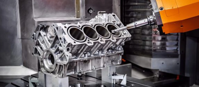
Even with tight control, some parts may require secondary machining.
Why Post-Casting Matters
- Machining can improve dimensional precision
- Finishing processes (grinding, polishing) may alter tolerances
- Improper handling or heat treatment can cause distortion
The integration of machining and finishing steps must be considered in the tolerance design stage.
6. Environmental and Human Factors
- Temperature and humidity in the workshop can affect metal cooling behavior.
- Operator skill plays a role in setting up machines and monitoring tolerances.
- Maintenance schedules ensure machinery and tooling remain accurate.
Even the best-designed part may fail tolerance requirements if production discipline is lacking.
Balancing Factors for Success
In reality, die casting tolerances are a balance between design intent, material selection, tooling precision, and process control. Overly strict tolerances may increase costs, while loose tolerances may compromise performance.
The key is collaboration between designers, engineers, and suppliers to set tolerances that are realistic, cost-effective, and meet functional needs.
Material Selection and Its Role in Tolerance Control
One of the most important influences on die casting tolerances is the choice of material. Different alloys behave differently during casting due to variations in thermal expansion, shrinkage rates, and mechanical properties. Selecting the right alloy can make the difference between a stable, precise part and one that fails tolerance requirements.
Aluminum Alloys
Aluminum is the most widely used die casting material.
Tolerance Characteristics
- Moderate shrinkage during solidification (≈ 1%)
- Good dimensional stability with controlled cooling
- Capable of achieving tight tolerances for automotive and aerospace applications
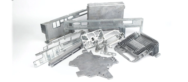
Applications
- Engine housings
- Electronic enclosures
- Aerospace brackets
Aluminum is a good balance between weight, strength, and tolerance control.
Zinc Alloys
Zinc offers some of the best tolerance control among die casting metals.
Tolerance Characteristics
- Excellent fluidity → fills thin sections easily
- Minimal shrinkage compared to aluminum
- Superior dimensional accuracy with fine details
Applications
- Consumer electronics housings
- Precision gears
- Lock components
When tight tolerances are critical, zinc is often the best choice.
Magnesium Alloys
Magnesium is valued for its lightweight properties, but it is more challenging in terms of tolerances.
Tolerance Characteristics
- Tends to warp during cooling due to high reactivity
- Requires careful process control to minimize distortion
- Machining may be needed to achieve strict tolerances
Applications
- Automotive lightweight parts
- Electronics casings
- Portable equipment housings
Magnesium provides weight savings but often requires compromises in tolerance precision.
Copper-Based Alloys
Copper and its alloys (such as brass and bronze) are less common in die casting but still important in specialized applications.
Tolerance Characteristics
- Strong and durable but prone to higher shrinkage
- Tolerance control is more difficult compared to aluminum and zinc
- Machining is often required for critical dimensions
Applications
- Plumbing fixtures
- Marine components
- Heavy-duty industrial parts
Copper alloys are chosen more for their strength and corrosion resistance than their tolerance performance.
How to Choose the Right Material for Tolerance Control
When selecting a material for die casting, consider:
- Functionality → What tolerance level is necessary for performance?
- Cost → Is machining acceptable, or must parts be cast to final dimensions?
- Production scale → High-volume projects may justify more precise alloys.
- Industry requirements → Automotive, aerospace, and electronics demand stricter tolerance control.
Conclusion of Material Impact
Material selection is a critical design decision. Choosing the wrong alloy can lead to distorted parts, excessive machining, or failed inspections. The right choice ensures that tolerances are realistic, achievable, and cost-effective.
Conclusion
Mastering die casting tolerances is the foundation of precision and quality. By understanding tolerance types, industry standards, influencing factors, and material selection, manufacturers can achieve consistent accuracy, reduce costs, and deliver reliable parts across industries.